Movable crane with height capable of being adjusted conveniently

A technology for moving cranes and adjusting heights, which is applied to cranes, hoisting equipment braking devices, load suspension components, etc. It can solve the problems of inability to quickly realize track conversion, limit the use range of cantilever cranes, and limit the use range of cranes, etc., and achieve good results. Lifting stability, saving labor intensity, novel design effects

Inactive Publication Date: 2016-03-23
ANHUI CHAOSHENG HOISTING MACHINERY CO LTD
View PDF0 Cites 3 Cited by
  • Summary
  • Abstract
  • Description
  • Claims
  • Application Information

AI Technical Summary

Problems solved by technology

[0002] Cantilever cranes, also known as cantilever cranes, have the advantages of convenient operation, flexible rotation, and large working space. They are energy-saving and efficient material handling equipment. With the continuous development of the economy, cantilever cranes have been widely used in economic construction. The use environment is mostly on the ground or at a position with a low height from the ground. The cantilever is rotated by pulling the suspension ring at the front end of the cantilever. The height cannot be adjusted, which limits the scope of use of the cantilever crane and cannot meet the requirements of more workers. Although some can adjust the length by adjusting the position of the bolt on the bolt hole, it weakens the strength of the structure itself and is inconvenient to adjust; at the same time, the crane It often needs to be moved, so the bottom is often equipped with a traveling mechanism. The existing crane traveling mechanism includes supports fixed on both sides of the lower end of the door seat. The supports are directly connected to the walking frame, and the walking frame is equipped with traveling wheels. The traveling mechanism can run safely and smoothly on parallel straight tracks. When there is a cross track and the track needs to be changed, the track change cannot be quickly realized, which reduces the working efficiency and limits the scope of use of the crane.

Method used


Image

  • Movable crane with height capable of being adjusted conveniently
  • Movable crane with height capable of being adjusted conveniently
  • Movable crane with height capable of being adjusted conveniently

Examples


Embodiment Construction

[0020] The technical solution of this patent will be further described in detail below in conjunction with specific embodiments.

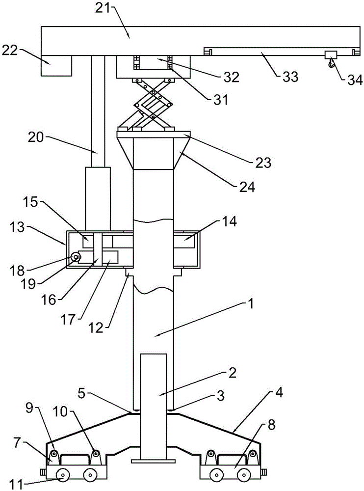
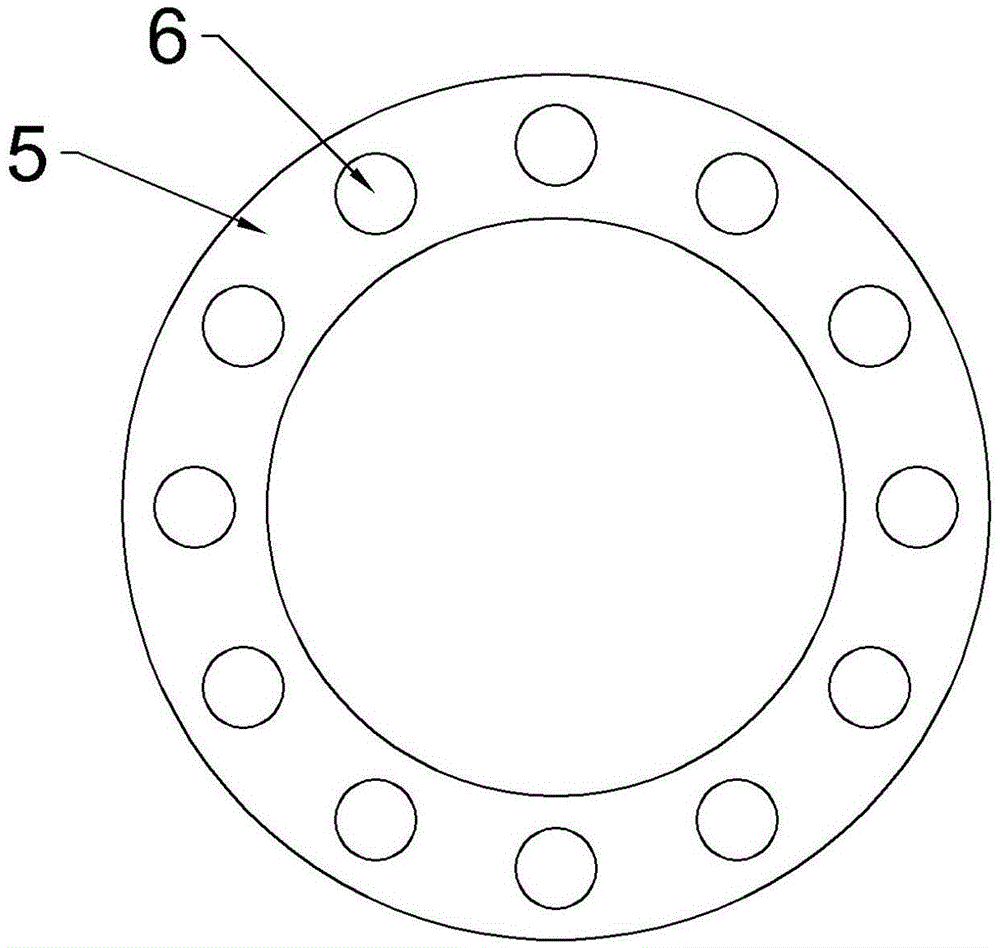
[0021] see Figure 1-3 , a mobile crane that is convenient for height adjustment, including a column 1, a jacking rod 2 is embedded in the bottom of the column 1, a protrusion 3 is connected to the lower part of the column 1, and a support beam 4 is connected to the jacking rod 2, The middle of the support beam 4 is provided with a ring 5, the top of the ring 5 is uniformly provided with a groove 6, and both sides of the bottom of the support beam 4 are provided with a connecting block 7, the connecting block 7 is connected with a walking frame 8, and the walking frame 8 Both sides of the upper part of the upper part are provided with a connecting plate 9, a pin shaft 10 is provided between the connecting plate 9 and the connecting block 7, and a roller 11 is provided at the lower end of the walking frame 8; The upper end of the lifter 12 is conne...


PUM


Abstract

The invention discloses a movable crane with the height capable of being adjusted conveniently. The movable crane comprises a stand column, a jacking rod is arranged at the bottom of the stand column in an embedded mode, protrusions are connected to the lower portion of the stand column, a support beam is connected to the jacking rod, a circular ring is arranged in the middle of the support beam, the two sides of the lower portion of the support beam are each provided with connecting blocks which are connected to a walking frame, an annular protrusion is arranged on the upper portion of the stand column, a gearbox is connected to the upper end of the annular protrusion, a telescopic rod is further connected to the left side of the gearbox, a cantilever beam is connected to the other end of the telescopic rod, a counterweight body is arranged on the left side of the lower portion of the cantilever beam, a support table is arranged on the top of the stand column, reinforcing plates are arranged on the outer sides of the support table, and a hydraulic support is arranged on the support table and comprises hydraulic cylinders and lower supports. The movable crane with the height capable of being adjusted conveniently has the advantages of being high in structural strength, large in bearing capacity, novel in design, convenient to use, convenient to reverse, safe and reliable.

Description

technical field [0001] The invention relates to a crane, in particular to a mobile crane with convenient height adjustment. Background technique [0002] Cantilever cranes, also known as cantilever cranes, have the advantages of convenient operation, flexible rotation, and large working space. They are energy-saving and efficient material handling equipment. With the continuous development of the economy, cantilever cranes have been widely used in economic construction. The use environment is mostly on the ground or at a position with a low height from the ground. The cantilever is rotated by pulling the suspension ring at the front end of the cantilever. The height cannot be adjusted, which limits the scope of use of the cantilever crane, and cannot meet the requirements of more workers. Although some lengths can be adjusted by adjusting the position of the bolt on the bolt hole, the strength of the structure itself is weakened, and the adjustment is inconvenient; at the sa...

Claims


Application Information

Patent Timeline
Patent Type & Authority Applications(China)
IPC IPC(8): B66C5/00B66C23/62B66C23/72
CPCB66C5/00B66C23/62B66C23/72B66C2700/01B66C2700/03
Inventor 王云祥
Owner ANHUI CHAOSHENG HOISTING MACHINERY CO LTD
Why Eureka
Try Eureka