Aerated concrete block separator

A kind of technology of air-entrained concrete and separator, which is applied in the direction of ceramic molding machine, auxiliary molding equipment, manufacturing tools, etc. It can solve the problems of large lifting and shaking of the clamping mechanism, affecting product quality, and high labor intensity, so as to improve the stability of lifting and lowering , Easy to transport and stack, reduce labor intensity

Inactive Publication Date: 2018-12-21
HENGYANG HENGYU LIGHTWEIGHT INSULATION MATERIAL CO LTD
View PDF5 Cites 3 Cited by
  • Summary
  • Abstract
  • Description
  • Claims
  • Application Information

AI Technical Summary

Problems solved by technology

[0004] The purpose of the present invention is to provide a kind of aerated concrete block separator, to solve the problem that manual operation is difficult to separate during the separation proposed in the above background technology, the labor intensity is high, and the concrete block is easy to be damaged, and the separation device of some separation equipment is lifted When the upper and lower blocks are separated, the upper and lower clamping mechanisms of the separation device move up and down greatly, the stability is not ideal, and the movement deviation is easy to cause the blocks to be clamped incorrectly. It is firm, and even damages the block when lifting and lowering, which affects the product quality. The existing device is more troublesome when lifting the concrete block.

Method used


Image

  • Aerated concrete block separator
  • Aerated concrete block separator
  • Aerated concrete block separator

Examples


Embodiment Construction

[0016] The following will clearly and completely describe the technical solutions in the embodiments of the present invention with reference to the accompanying drawings in the embodiments of the present invention. Obviously, the described embodiments are only some, not all, embodiments of the present invention. Based on the embodiments of the present invention, all other embodiments obtained by persons of ordinary skill in the art without making creative efforts belong to the protection scope of the present invention.

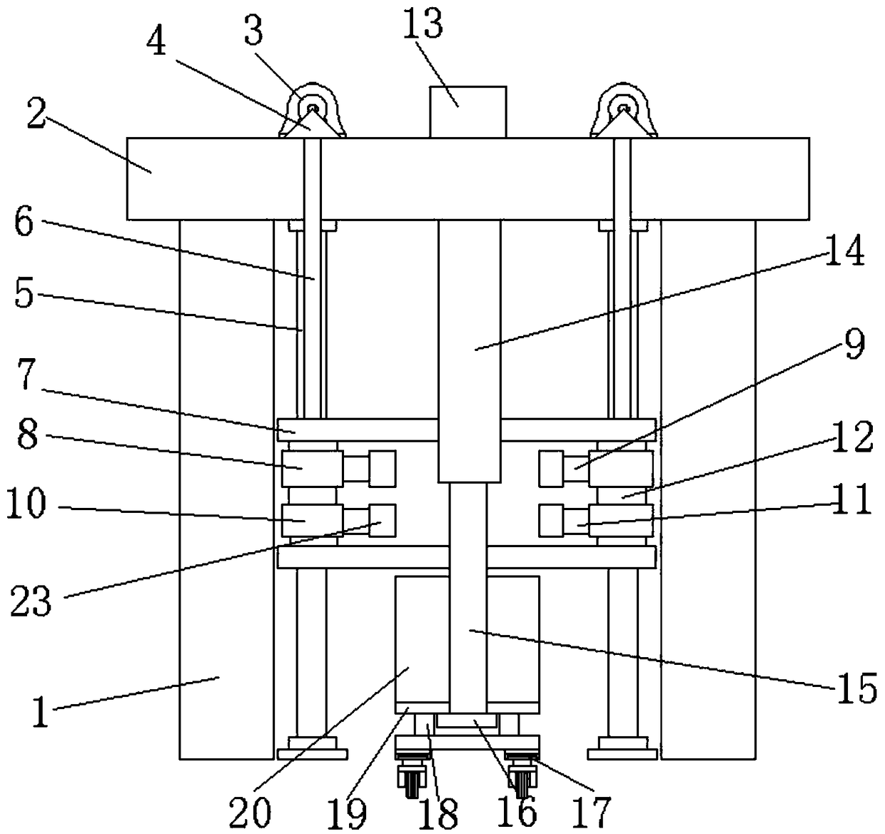
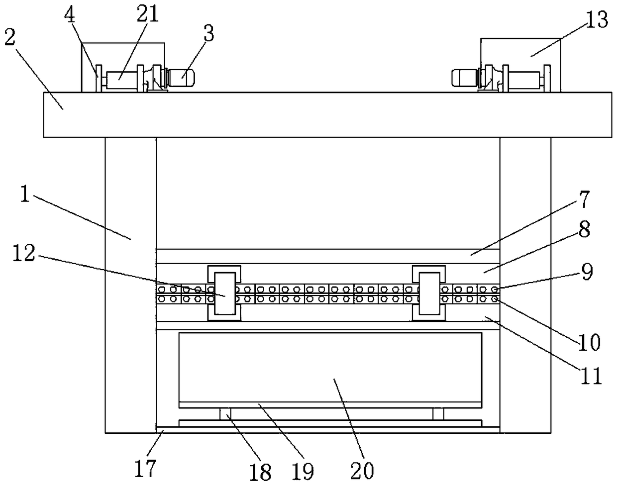
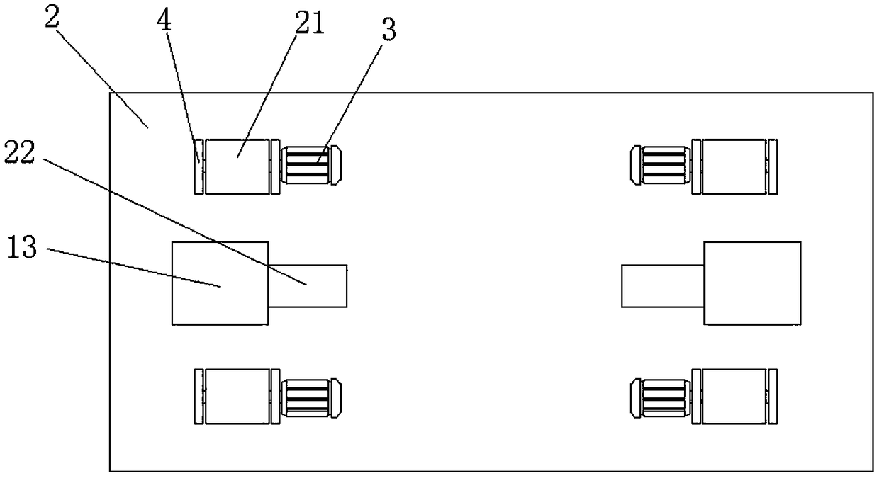
[0017] see Figure 1-3 , an embodiment provided by the present invention: an aerated concrete block separator, including a column 1, a beam 2 is arranged on the upper end of the column 1, a slide bar 5 is fixed on the bottom end of the beam 2, and a Rotating motor 3, the output end of rotating motor 3 is connected with rotating roller 21, and the two ends of rotating roller 21 are all provided with fixed seat 4, and fixed seat 4 is fixed on the upper end of be...


PUM


Abstract

The invention discloses an aerated concrete block separator. The aerated concrete block separator comprises a stand column; a slide rod is fixed at the bottom end of a cross beam; a rotating motor ismounted at the upper end of the cross beam; the end, far from the cross beam, of a steel wire rope is connected with a lifting frame; an upper clamping beam is arranged under the lifting frame; a first clamping oil cylinder is arranged on the side, far from the stand column, of the upper clamping beam; the bottom end of the upper clamping beam is connected with a jacking oil cylinder; the lower end of the jacking oil cylinder is connected with a lower clamping beam; and a second clamping oil cylinder is arranged on the side, far from the stand column, of the lower clamping beam. The rotating motor drives the lifting frame to move up and down; upper and lower layers of blocks are clamped through the first clamping oil cylinder and the second clamping oil cylinder; the jacking oil cylinder pushes an upper layer of clamping parts to ascend to realize the surface separation of upper and lower layers of blocks, so that the working efficiency is high, and the labor intensity is reduced; andthrough sliding of the upper clamping beam and the lower clamping beam on the surface of the slide rod, the shaking phenomenon during lifting of the separator is prevented.

Description

technical field [0001] The invention relates to the technical field of production of aerated concrete blocks, in particular to an aerated concrete block separator. Background technique [0002] After the autoclaved aerated concrete block is cut, during the autoclaved curing process, due to the negative pressure of the vacuum and the autoclaved hardening, the hydration product extends to the opposite side through the material powder in the gap during the hydrothermal synthesis reaction. Crystallization, which reconnects the already separated embryoid bodies. [0003] It is difficult to separate by manual operation during separation, the labor intensity is high, and the concrete block is easy to be damaged. When the separation device of some separation equipment is raised and lowered, the roller moves along the raceway. When separating the upper and lower blocks, the separation device The clamping mechanism of the upper and lower layers shakes a lot, the stability is not idea...

Claims


Application Information

Patent Timeline
Patent Type & Authority Applications(China)
IPC IPC(8): B28B17/00
CPCB28B17/0018
Inventor 谭泽林
Owner HENGYANG HENGYU LIGHTWEIGHT INSULATION MATERIAL CO LTD
Why Eureka
Try Eureka