
Patsnap Eureka
For R&D, Patsnap Eureka makes reading and utilizing patents & technical documents easy.
Patsnap Eureka AIR
Designed for self-driven R&D workflows. Generate viable solutions, solve complex R&D challenges, empower your innovation with AI.

Patsnap Eureka Materials
Designed for material experts only. Revolutionize your material R&D, from search, analyze, to developing new materials.

TechResearch
Generate reliable direction feasibility study reports for your R&D in just a few steps.

TechSeek
Discover and master advanced knowledge NOW. Basics, ideas, possibilities, all at once.

TechMind
As an expert in R&D Theories, TechMind can generates customized viable solutions instantly.

TechRisk
Analyze your overall solution with one click, know your potential R&D risks in advance.

TechMonitor
Get weekly tech updates, stay abreast of the latest tech innovations and key insights.
Electroplating hanger
A technology of electroplating hanger and support frame, which is applied in the direction of electrolysis process and electrolysis components, etc., which can solve the problems affecting the uniformity of the plating layer of the plated parts and affect the plating layer, and achieve the effect of simple structure, improved uniformity and convenient use
- Summary
- Abstract
- Description
- Claims
- Application Information
AI Technical Summary
Problems solved by technology
Method used
Image

Examples
Embodiment Construction
[0010] An implementation manner of the present invention will be briefly described below in conjunction with the accompanying drawings.
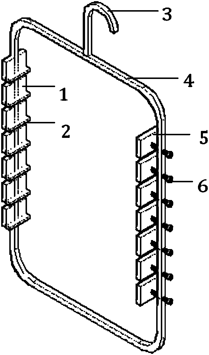
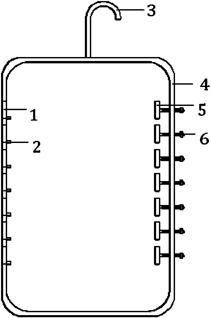
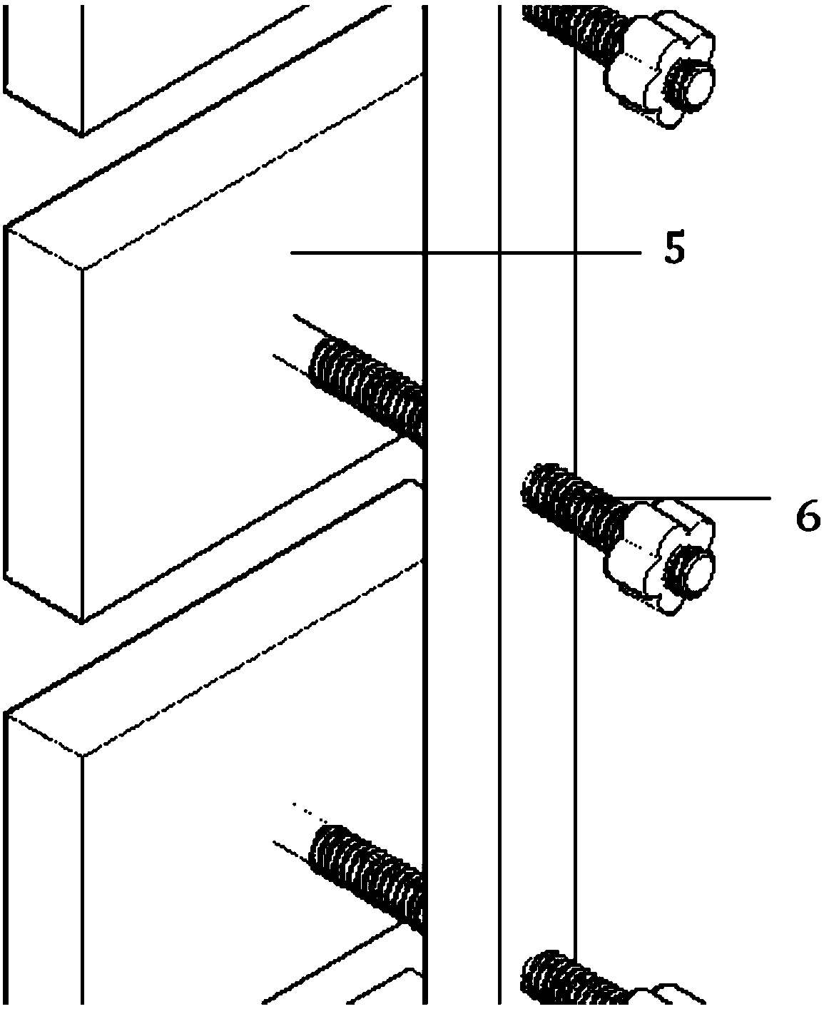
[0011] Such as figure 1 , figure 2 with image 3 An electroplating hanger, comprising a hook 3, a support frame 4, the support frame 4 is a quadrilateral frame; two vertical frames of the support frame 4 are respectively provided with several fixing blocks 1 and locking blocks 5; The fixed block 1 is directly fixed on the frame of the support frame 4, and the locking block 5 is fixed on the frame of the support frame 4 by a locking nut 6. The fixed block 1 and the locking block 5 Corresponding positions, the plated parts can be placed between the fixed block 1 and the locking block 5, and the plated parts can be clamped by turning the locking nut 6. In this clamping method, the plated parts (except both ends) are dipped in the electroplating solution , there is no obstacle to block the movement of ions, which can make the ions in the ele...
PUM
 Abstract
Description
Claims
Application Information
 - R&D Engineer
- R&D Manager
- IP Professional
- Industry Leading Data Capabilities
- Powerful AI technology
- Patent DNA Extraction
Browse by: Latest US Patents, China's latest patents, Technical Efficacy Thesaurus, Application Domain, Technology Topic, Popular Technical Reports.
© 2024 PatSnap. All rights reserved.Legal|Privacy policy|Modern Slavery Act Transparency Statement|Sitemap|About US| Contact US: help@patsnap.com