Self-reset viscoelastic energy dissipation steel beam

A viscoelastic, self-resetting technology, applied in beams, joists, trusses, etc., to avoid deformation and expansion problems, control residual deformation, and control repair costs

Pending Publication Date: 2018-05-11
CHONGQING UNIV
View PDF0 Cites 6 Cited by
  • Summary
  • Abstract
  • Description
  • Claims
  • Application Information

AI Technical Summary

Problems solved by technology

[0004] The purpose of the present invention is to solve the expansion deformation coordination problem of frame floor and other components, and at the same time provide a self-resetting viscoelastic energy-dissipating steel beam structure with stable reset performance and bearing capacity, and good energy dissipation capacity, especially It is suitable for long-span steel frame structure systems with high requirements on mechanical performance and reset effect

Method used


Image

  • Self-reset viscoelastic energy dissipation steel beam
  • Self-reset viscoelastic energy dissipation steel beam
  • Self-reset viscoelastic energy dissipation steel beam

Examples


Embodiment 1

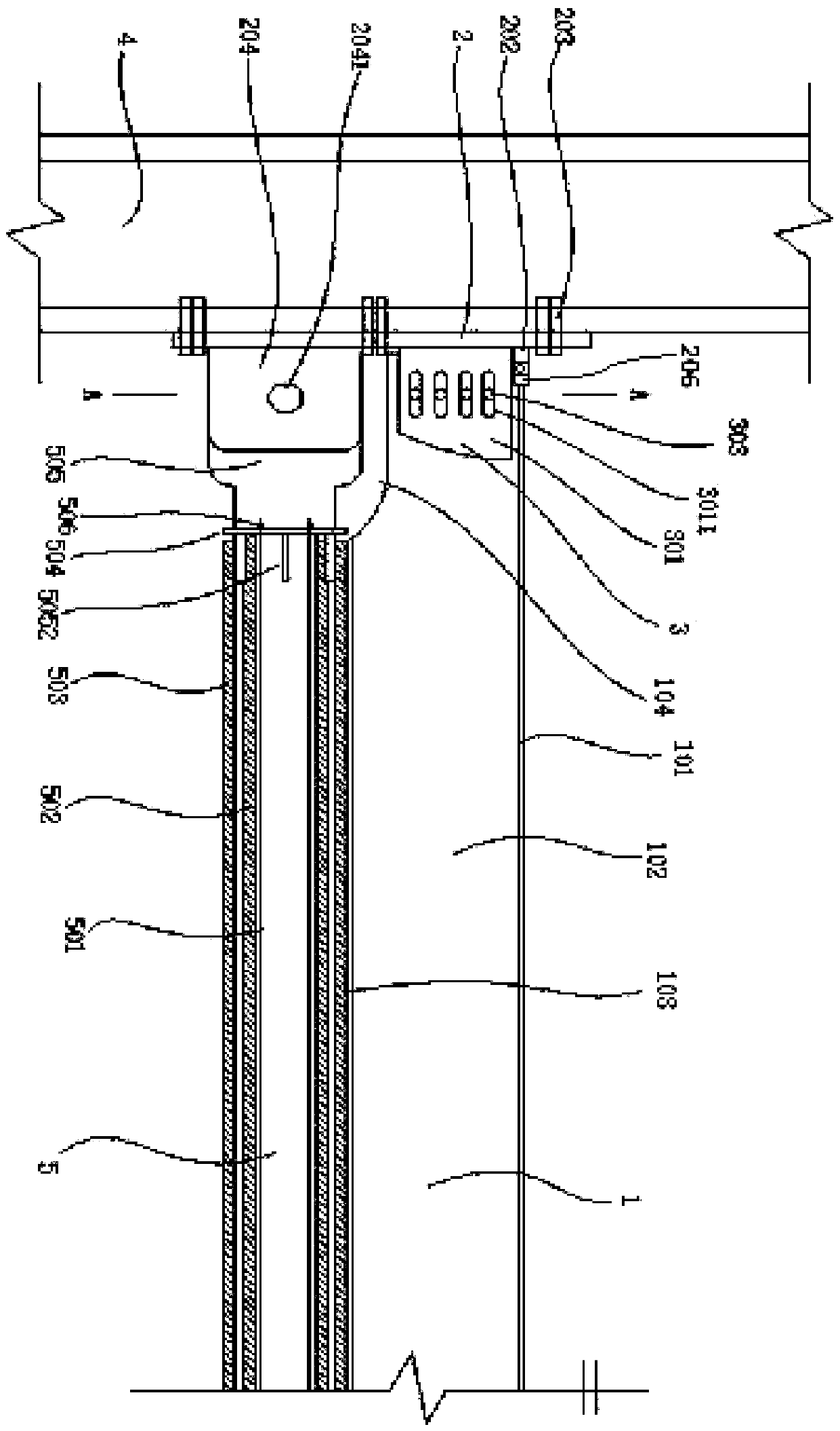
[0040] see figure 1 , self-resetting viscoelastic energy-dissipating steel beams, including I-shaped steel beams 1, beam-end connecting pads 2, viscoelastic energy-dissipating bodies 3, H-shaped steel frame columns 4 and self-resetting systems 5.

[0041]One side of the beam end connecting backing plate 2 is connected to the flange of the H-shaped steel frame column 4 through high-strength bolts 203 , and the other side is welded with connector I 202 and connector II 204 .

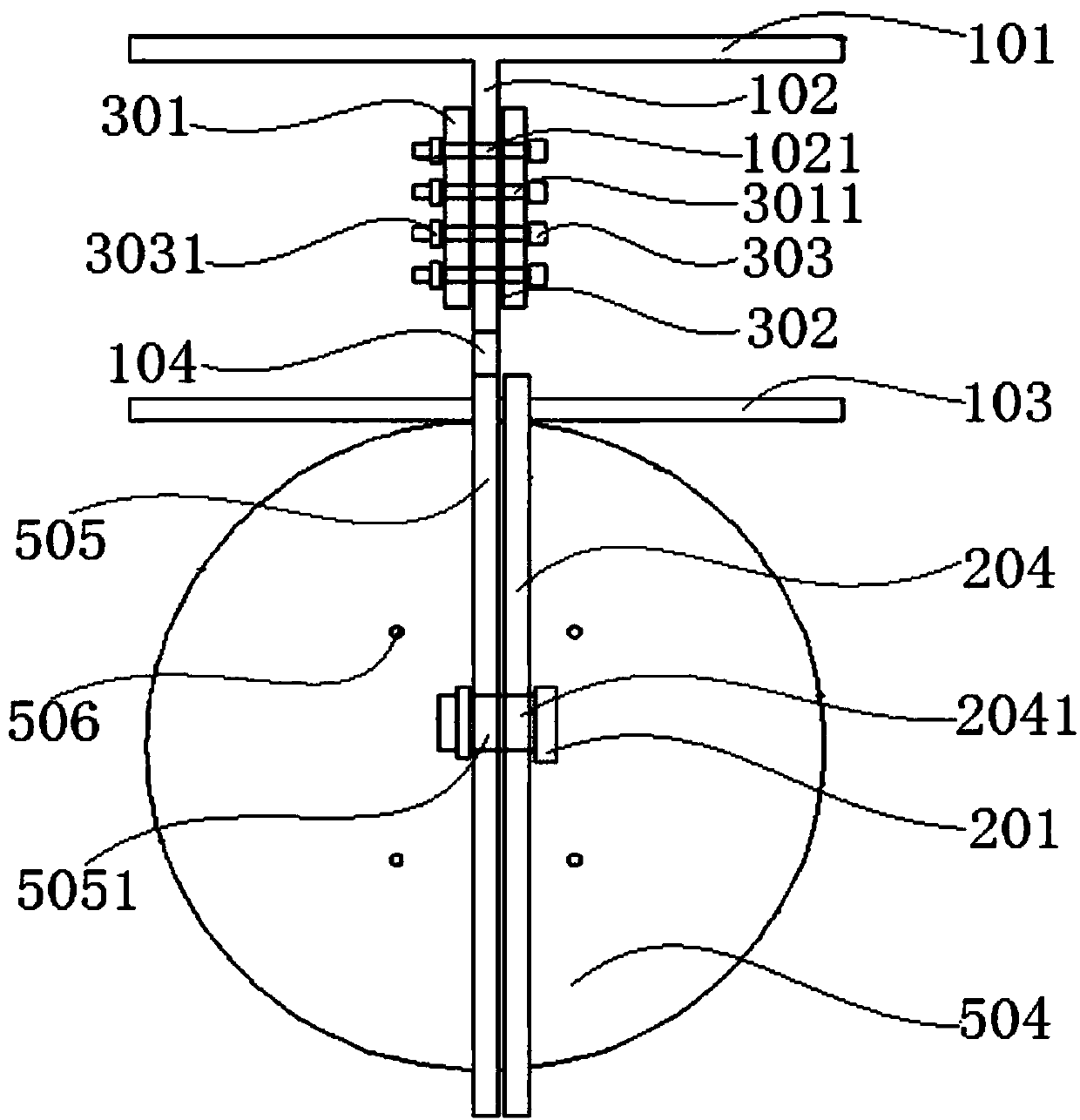
[0042] see figure 1 with figure 2 , the viscoelastic energy dissipating body 3 includes two shear connection plates 301 welded on the beam end connection backing plate 2 . A viscoelastic material 302 is attached to the inner side of the shear connection plate 301 . A number of slotted holes 3011 are opened on the shear connecting plate 301 .

[0043] The I-beam 1 has a groove 104 and a groove 105 . The groove 104 is formed by cutting off the lower flange of the end and the part of the end web near th...

Embodiment 2

[0051] The self-resetting viscoelastic energy-dissipating steel beam includes an I-shaped steel beam 1, a beam end connecting backing plate 2, a viscoelastic energy-dissipating body 3, an H-shaped steel frame column 4 and a self-resetting system 5.

[0052] One side of the beam end connecting backing plate 2 is connected to the flange of the H-shaped steel frame column 4 through high-strength bolts 203 , and the other side is welded with connector I 202 and connector II 204 .

[0053] The viscoelastic energy dissipating body 3 includes two shear connection plates 301 welded on the beam end connection backing plate 2 . A viscoelastic material 302 is attached to the inner side of the shear connection plate 301 . A number of slotted holes 3011 are opened on the shear connecting plate 301 .

[0054] The I-beam 1 has a groove 104 and a groove 105 . The groove 104 is formed by cutting off the lower flange of the end and the part of the end web near the lower flange. The groove 10...


PUM


Abstract

The invention provides a self-reset viscoelastic energy dissipation steel beam. In the self-reset viscoelastic energy dissipation steel beam, an I-shaped steel beam is connected with frame columns through a beam end connecting cushion plate, a viscoelastic energy dissipation body and a self-reset system. According to the self-reset viscoelastic energy dissipation steel beam structure, stable resetperformance and the load-carrying capacity are achieved, and meanwhile the good energy dissipation capacity is achieved. Through the joint design of the upper and lower flange ends of the beam, the space between the frame columns is always kept constant, displacement response of a frame under the load effect is concentrated on relative displacement between an inner sleeve and an outer sleeve, andthus the problem of deformation expansion caused by the self-reset frame through joint energy dissipation is effectively avoided; residual deformation of the structure is effectively controlled through the reset system; and the self-reset viscoelastic energy dissipation steel beam is especially suitable for a large-span steel frame structure system with high requirements for stress performance and the reset effect.

Description

technical field [0001] The invention relates to a novel steel beam, in particular to a self-resetting energy-dissipating steel beam, which belongs to the technical field of structural engineering. Background technique [0002] The traditional steel frame structure mainly relies on the plastic deformation of structural components such as beams and columns to dissipate the earthquake energy. After the earthquake, the structure will produce large plastic residual deformation, making it difficult to repair or even demolition and reconstruction of the structure, resulting in huge economic losses. . The self-resetting structure is a new type of structure designed to reduce or eliminate the "residual deformation" of the structure. A typical self-resetting structure system is mainly composed of two parts: a self-resetting system and an energy dissipation system. The self-resetting system includes resetting components such as beam and column nodes, prestressed steel strands and shap...

Claims


Application Information

Patent Timeline
IPC IPC(8): E04C3/04E04C3/08E04B1/98E04H9/02
CPCE04C3/04E04C3/08E04H9/021Y02A30/30
Inventor 杨溥
Owner CHONGQING UNIV
Why Eureka
Try Eureka