Packaging structure of flip chip type filter

A packaging structure and flip-chip technology, which is applied in the field of filters, can solve the problems of unshielded chips and inflow of encapsulation glue, etc., and achieve the effect of improving performance

Pending Publication Date: 2018-05-11
ZHEJIANG HUAYUAN MICRO ELECTRONICS TECH CO LTD
View PDF6 Cites 2 Cited by
  • Summary
  • Abstract
  • Description
  • Claims
  • Application Information

AI Technical Summary

Problems solved by technology

[0005] In order to solve the problems in the prior art, the present invention provides a flip-chip filter packaging structure, this structure can prevent the encapsulation glue from flowing between the substrate and the chip, and at the same time solve the problem that the chip has no shielding

Method used


Image

  • Packaging structure of flip chip type filter
  • Packaging structure of flip chip type filter
  • Packaging structure of flip chip type filter

Examples


Embodiment Construction

[0023] The present invention will be described in detail below with reference to the accompanying drawings.

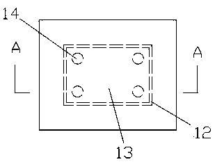
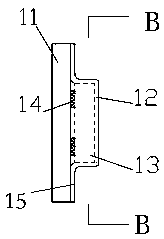
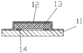
[0024] Such as Figure 1-Figure 4 As shown, this embodiment provides a flip-chip 13-type filter packaging structure, including a substrate 11, a protective coating 12, a chip 13, and a connecting pin 14. The protective coating 12 has a plate-shaped body, and the center of the protective coating 12 13 Grooves with matching sizes, connecting portions 15 are formed around the grooves, and the chips 13 are keyed to the substrate 11 through the connecting pins 14, the protective coating 12 is fixed on the substrate 11 through the connecting portions 15, and the chip 13 is encapsulated in the grooves .

[0025] Specifically, in the packaging mechanism, the front surface of the substrate 11 is flat, the protective coating 12 is made of metal material, and the chip 13 is placed in the internal groove of the protective coating 12. After the protective coating 12 and the substrate 1...


PUM


Abstract

The invention relates to a filter, specifically a packaging structure of a flip chip type filter. The packaging structure of the flip chip type filter comprises a substrate, a protection plated layer,a chip and connecting pins, wherein the protection plated layer main body is plate-like, a groove matched with the size of the chip is formed in the central position thereof, and a connecting part isformed in the periphery of the groove; the chip and the substrate are in key connection through the connecting pins; and the protection plated layer is fixed on the substrate through the connecting part, and the chip is packaged in the groove. In the packaging structure, the exterior of the chip is covered with a hollow cavity protection plated layer, so that attachment of an encapsulating adhesive on a transducer on the surface of the chip is prevented, and product performance is improved effectively; and meanwhile, the hollow cavity protection plated layer adopts a metal material, so that ashielding function is realized.

Description

Technical field [0001] The invention relates to a filter, in particular to a packaging structure of a flip-chip filter. Background technique [0002] The packaging of the flip-chip filter generally adopts the flip-chip mounting on the substrate, and the encapsulant is used to seal the chip in the substrate and the encapsulant. This packaging structure has the following problems: [0003] 1. In the current packaging structure, the encapsulant is directly coated on the outside of the chip. Since the substrate and the chip are bonded together by gold balls, a cavity is formed between the substrate and the chip, and part of the encapsulant will flow into the substrate. In the cavity between the chip and the chip, part of the encapsulant adheres to the transducer on the chip surface, which affects the performance of the product. [0004] 2. The encapsulant is directly coated on the outside of the chip without shielding function. Summary of the invention [0005] In order to solve the pr...

Claims


Application Information

Patent Timeline
Patent Type & Authority Applications(China)
IPC IPC(8): H01L23/29H01L23/31H01L23/60
CPCH01L23/60H01L23/29H01L23/3114
Inventor 刘长顺刘绍侃张正张水清张修华
Owner ZHEJIANG HUAYUAN MICRO ELECTRONICS TECH CO LTD
Why Eureka
Try Eureka