Video quality monitoring method, video quality monitoring server and equipment

A technology for monitoring server and video quality, which is applied in the field of video services, and can solve problems such as low computing overhead, strict computing overhead restrictions, and high computing overhead

Active Publication Date: 2018-05-11
HUAWEI TECH CO LTD
View PDF4 Cites 0 Cited by
  • Summary
  • Abstract
  • Description
  • Claims
  • Application Information

AI Technical Summary

Problems solved by technology

[0004] In fact, the calculation overhead of the VMOS algorithm mainly depends on the calculation source MOS. The probe server can be deployed at the head end, which has strong computing power and a high tolerance for calculation overhead. The practical application of the VMOS algorithm requires a high-precision source MOS algorithm. However, high-precision source MOS algorithms require in-depth decoding of video sources, and the calculation overhead is high. There is no problem in using such source MOS algorithms to calculate MOS points at the head end, but the computing power of network devices and terminal devices is weak, which greatly affects the calculation overhead. The restrictions are strict, so network devices and terminal devices cannot use the high-precision source MOS algorithm of deep decoding, but can only use the source MOS algorithm with low computational overhead that does not involve deep decoding, and the source MOS calculated in this way cannot accurately represent the video source The quality of the actual application is meaningless, and the VMOS score calculated from this is not accurate
Furthermore, the video quality monitoring server cannot accurately monitor the video service quality according to the VMOS indicators reported by each device, which seriously affects the effect of video service quality monitoring
In particular, it is very important to obtain accurate source MOS scores on the terminal, which also leads to great challenges in the deployment of VMOS algorithms.

Method used


Image

  • Video quality monitoring method, video quality monitoring server and equipment
  • Video quality monitoring method, video quality monitoring server and equipment
  • Video quality monitoring method, video quality monitoring server and equipment

Examples


Embodiment Construction

[0049] The following will clearly and completely describe the technical solutions in the embodiments of the present invention with reference to the accompanying drawings in the embodiments of the present invention. Obviously, the described embodiments are only some, not all, embodiments of the present invention. Based on the embodiments of the present invention, all other embodiments obtained by persons of ordinary skill in the art without creative efforts fall within the protection scope of the present invention.

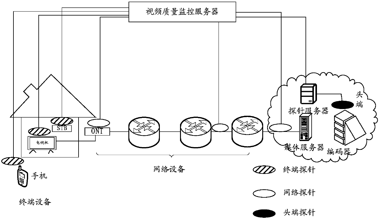
[0050] figure 1 Shown is the architecture diagram of the video quality monitoring system. The system includes a video quality monitoring server and a device cluster. Wherein, the device cluster includes the head end to be monitored, network devices and terminal devices, and a probe server deployed at the head end. Among them, the head end is used to provide video streams, including: head end encoder (encoder), streaming server, in addition, a probe server (probe ...


PUM


Abstract

The embodiment of the invention provides a video quality monitoring method, a video quality monitoring server and equipment, and relates to the field of the video service. Network equipment and terminal equipment can multiplex a source MOS computed by a head end, an operation of independently computing the source MOS is unnecessary, and the computing expenditure is saved. The method comprises thefollowing steps: receiving a compression quality score of a video stream sent by the head end, and the first transmission quality score of the video stream by a video quality monitoring server; computing the first video mean quality score of the video stream according to the compression quality score and the first transmission quality score; receiving the second transmission quality score of the video stream sent by the network equipment and the third transmission quality score sent by the terminal equipment. The third video mean quality score of the video stream is computed according to the compression quality score of the vide stream and the third transmission quality score obtained through head end computation; and the video quality monitoring is performed according to the compression quality score, the first transmission quality score, the first video mean quality score, the second transmission quality score, the third transmission quality score and the third video mean quality score.

Description

technical field [0001] The invention relates to the field of video services, in particular to a video quality monitoring method, a video quality monitoring server and equipment. Background technique [0002] With the advancement of communication technology and multimedia technology, network video services such as IPTV (Internet Protocol Television, Internet Protocol Television), video telephony, and network video on demand have been widely developed. For video service providers, the core issue of video services is to ensure the user experience of the terminal (that is, the terminal that plays the video), which requires accurate evaluation of the video quality experience and further implementation of fault demarcation and location. At present, VMOS (Video Mean Opinion Score, video average opinion score index is the core index in video quality experience evaluation. VMOS is based on the source MOS score (that is, the compression quality of the video source, used to evaluate th...

Claims


Application Information

Patent Timeline
Patent Type & Authority Applications(China)
IPC IPC(8): H04L29/06
CPCH04L65/80
Inventor 鞠增伟
Owner HUAWEI TECH CO LTD
Why Eureka
Try Eureka