
Injector test device

A testing device and injector technology, which can be applied to fuel injection devices, measuring devices, pump testing, etc., can solve problems such as high cost and high wear, and achieve low-cost effects.

Active Publication Date: 2018-05-11
ROBERT BOSCH GMBH
View PDF9 Cites 1 Cited by
  • Summary
  • Abstract
  • Description
  • Claims
  • Application Information

AI Technical Summary

Problems solved by technology

[0004] High pressure hoses have a higher cost and are subject to higher wear than steel pipes

Method used


Image

  • Injector test device
  • Injector test device
  • Injector test device

Examples


Embodiment Construction

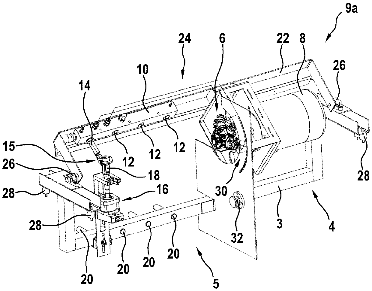
[0021] figure 1 A perspective front view of an injector test device 2 with a structural assembly 9a according to one embodiment of the invention is shown. Figure 2a and 2b A perspective view of a structural assembly 9 a comprising the functional elements of the injector testing device 2 is shown from two different angles.

[0022] The injector test device 2 includes the figure 1 , 2a The pressure generating area 4 shown on the right of and 2b and the test area 5 shown on the left respectively.

[0023] The injector testing device 2 has a carrier frame 3 which carries a fluid pump (high pressure pump) 6 and a motor 8 designed to drive the fluid pump 6 .

[0024] The pivotable frame 22 is supported on the carrier frame 3 via two pillow blocks 26 in such a way that the pivotable frame can pivot about a horizontal axis. This makes it possible to adjust the pivotable frame 22 about a horizontal axis from horizontal to vertical at any desired angle. The pivotable frame 22 can...


PUM


Abstract

An injector test device (2) comprises a fluid pump (6), designed to pump a test oil; a motor (8), mechanically connected to the fluid pump (6) and designed to drive the fluid pump (6); and a rail (10)designed to accommodate the test oil pumped by the fluid pump (6) and for fluid communication with at least one injector (18) to be tested. The fluid pump (6), the motor (8) and the rail (10) are elastically mounted in the injector test device (2) as a common assembly (9a; 9b).

Description

technical field [0001] The invention relates to an injector testing device. Background technique [0002] To test the injectors in the injector test rig, test oil is brought from the high-pressure pump to the required pressure. For this purpose, a high-pressure pump ("common rail pump") is driven by a drive motor. The drive motor and high-pressure pump are usually elastically supported on rubber buffers to dampen vibrations during operation. For further guidance of the test oil under high pressure, a high-pressure pump is connected to a pressure accumulator or a high-pressure rail. [0003] Since the high-pressure pump moves during operation relative to the pressure accumulator or the high-pressure rail due to the elastic mounting, this connection must be designed flexibly, for example in the form of a high-pressure hose. Especially due to the movements that occur during operation, steel pipes cannot be used for this. [0004] High pressure hoses have a higher cost and a...

Claims


Application Information

Patent Timeline
Patent Type & Authority Applications(China)
IPC IPC(8): F02M65/00G01M15/02F04B51/00
CPCF02M65/00F04B51/00G01M15/02F02M65/001
Inventor A.巴塔R.霍斯D.施特拉克
Owner ROBERT BOSCH GMBH
Learn More