
Gasket

A gasket and main body technology, applied in the field of gaskets, can solve the problems of increasing the number of parts, increasing the cost, and damaging the wall surface.

Inactive Publication Date: 2018-05-11
NOK CORP
View PDF9 Cites 2 Cited by
  • Summary
  • Abstract
  • Description
  • Claims
  • Application Information

AI Technical Summary

Problems solved by technology

In this case, the use of positioning pins can also be considered, but there are problems in that it is not suitable for small products and the number of parts increases, which increases the cost
[0005] However, in this case, there is a problem that the length to the protrusion of the locking portion needs to be individually set according to the thickness of the flange portion or the dimension to the recess.
Moreover, when the side wall surface adjacent to the other sealing surface is a flat surface without a portion for locking the protrusion, it cannot be used at all.
[0006] Patent Document 3 discloses a structure in which protrusions are abolished, and flat-shaped locking portions are bent toward the inside at an acute angle and held by its elastic force. However, there is a problem of damaging the opposing wall surface when the gasket is assembled.

Method used


Image

  • Gasket
  • Gasket
  • Gasket

Examples


no. 1 approach

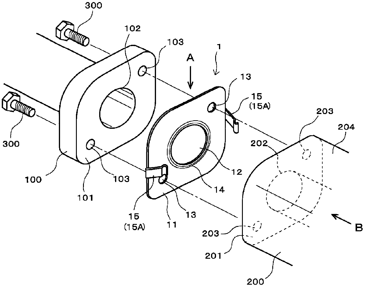
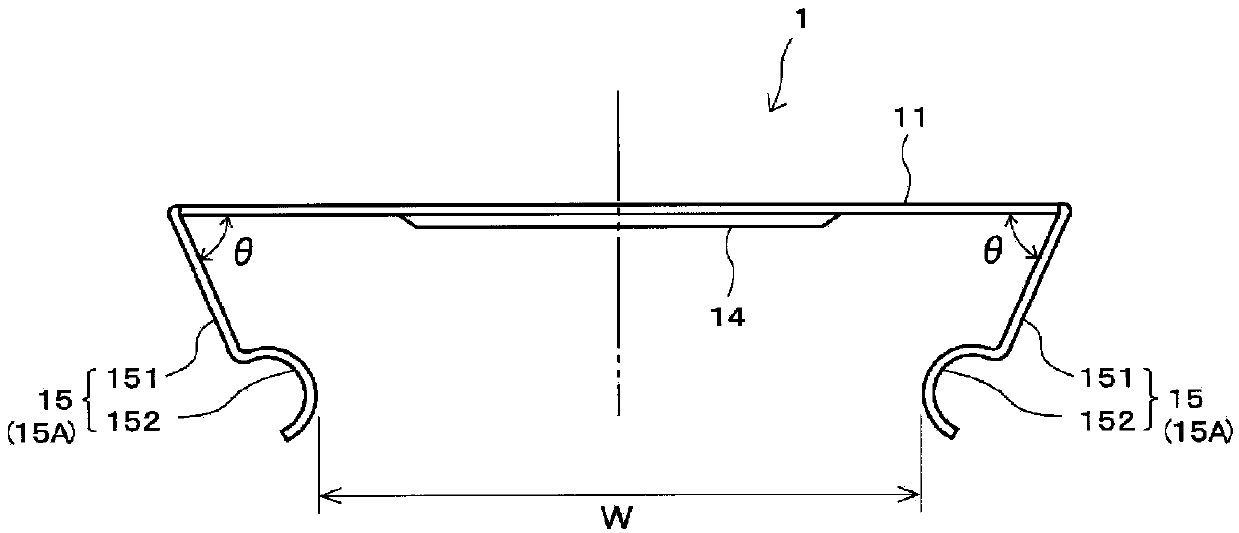
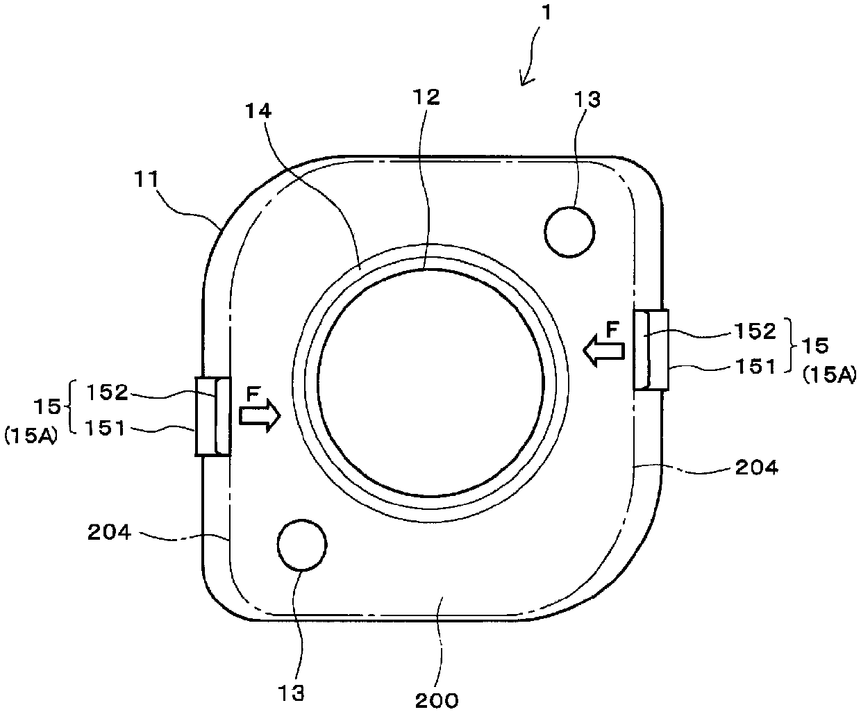
[0037] figure 1 It is an exploded perspective view showing the assembled state of the gasket according to the first embodiment of the present invention, figure 2 It is viewed from the direction of A figure 1 A side view of the gasket shown, image 3 From figure 1 B direction observation in figure 1 As shown in the diagram of the assembled state of the gasket, Figure 4 is description figure 1 The diagram showing the effect of the gasket, Figure 5 is description figure 1 A diagram showing an example of the assembly method of the spacer.

[0038] Such as figure 1 As shown, a gasket 1 is disposed between the opposing sealing surfaces 101 , 201 of a pair of components 100 , 200 . Openings 102 , 202 through which a fluid passes and bolt holes 103 , 203 are provided on the respective members 100 , 200 .

[0039] The gasket 1 is formed with an opening 12 and a bolt hole 13 on the gasket main body 11. The gasket main body 11 is made of metal substrates such as stainless st...

no. 2 approach

[0054] Figure 8 The gasket according to the second embodiment of the present invention is shown, (a) is a perspective view of the gasket, (b) is a figure 1 The figure in which the assembled state of the spacer shown in (a) is seen from the same direction as B direction. due to Figure 1 to Figure 7 Portions assigned the same reference numerals have the same structure, and therefore descriptions of these portions are referred to above, and are omitted here.

[0055] In this washer 2 , among the pair of locking claws 15 , 15 arranged to face each other across the opening 12 , one locking claw 15 forms an angle θ with the washer main body 11 of The first locking claw portion 15A is formed by bending toward the inside at an acute angle, and the other locking claw portion 15 is formed by bending at a right angle from the washer main body 11 . Hereinafter, in this specification, when referring only to the locking claw portion 15 bent and formed at the right angle, it is referred...

no. 3 approach

[0061] Figure 9 The gasket according to the third embodiment of the present invention is shown, (a) is a perspective view of the gasket, and (b) is a figure 1 The figure in which the assembled state of the spacer shown in (a) is seen from the same direction as B direction. due to Figure 1 to Figure 8 Portions assigned the same reference numerals have the same structure, and therefore descriptions of these portions are referred to above, and are omitted here.

[0062] The spacer 3 is in the Figure 1 ~ Figure 3 The shown washer 1 has a structure in which a pair of second locking claws 15B, 15B are added so as to face each other across the opening 12 . Such as Figure 9 As shown in (b), the first locking claws 15A, 15A and the second locking claws 15B, 15B are arranged at positions rotated by 90° around the opening 12 .

[0063] When the gasket 3 is assembled to the component 200, as in the case of the gasket 1, the gasket main body 11 can be self-held on the sealing surf...


PUM


Abstract

The present invention addresses the problem of providing a gasket configured so that, during the mounting of the gasket to a counterpart member, the gasket can be self-retained without requiring a catch formed on the gasket body to be engaged with the counterpart member and will be unlikely to damage a counterpart wall surface. In order to solve this problem, the gasket is configured so that at least two catches (15) coming in contact with sidewall surfaces adjacent to a counterpart seal surface will be formed in a protruding manner on the gasket body (11) comprising a metallic base plate, thecatches (15) respectively having curved sections (152) formed at the front ends of the catches (15), which come in contact with the sidewall surfaces, at least one of the catches (15) being formed bent toward the inner side of the gasket body (11) so that the angle formed between the gasket body (11) and the at least one of the catches (15) will be an acute angle, the spring force of the at leastone of the catches (15), which is formed bent to the acute angle, pressing the bent section (152) against a sidewall surface to cause the gasket body (11) to be self-retained on the counterpart sealsurface.

Description

technical field [0001] The present invention relates to a gasket. Specifically, at least two locking claws are protrudingly formed on a gasket body made of a metal substrate, and the locking claws are in contact with a side wall surface adjacent to a counterpart sealing surface. gasket. Background technique [0002] Seal between two parts by sandwiching a gasket between them to prevent sealing fluid from leaking to the outside. The assembly of the gasket is carried out by placing the gasket on the opposite sealing surface of one part, covering the other part, and then fastening the two parts with bolts. [0003] When the gasket is placed on the counterpart sealing surface, the position of the gasket may shift or fall off from the counterpart sealing surface. It is especially obvious when the opposite sealing surface is horizontal or downward. In this case, the use of positioning pins can also be considered, but there are problems in that it is not suitable for small produ...

Claims


Application Information

Patent Timeline
Patent Type & Authority Applications(China)
IPC IPC(8): F16J15/08F16B2/24F16B5/02
CPCF16B5/02F16B2/245F16J15/0818F16J15/061F16J15/08F16B2/24
Inventor 小岛康史
Owner NOK CORP
Features
  • Generate Ideas
  • Intellectual Property
  • Life Sciences
  • Materials
  • Tech Scout
  • Unparalleled Data Quality
  • Higher Quality Content
  • 60% Fewer Hallucinations
Learn More