Component alignment

One component, one part technology, applied in the field of component alignment, can solve problems such as high alignment cost and expensive equipment

Active Publication Date: 2018-05-11
FINISAR
View PDF5 Cites 2 Cited by
  • Summary
  • Abstract
  • Description
  • Claims
  • Application Information

AI Technical Summary

Problems solved by technology

Active alignment and similar processes can be relatively slow and may require relatively expensive equipment, which can result in high alignment costs

Method used


Image

  • Component alignment
  • Component alignment
  • Component alignment

Examples


Embodiment Construction

[0015] The expectation is that the passive alignment of optoelectronic components could be conceptually similar to fitting components together like a very precise jigsaw puzzle. Passive alignment can be relatively inexpensive, especially compared to active alignment. However, limitations in the physical accuracy of low-cost materials such as plastics and glass have hindered the fabrication of lenses, circuit boards, and low-cost mechanical components with the inherent accuracy sought for high-speed optoelectronic devices.

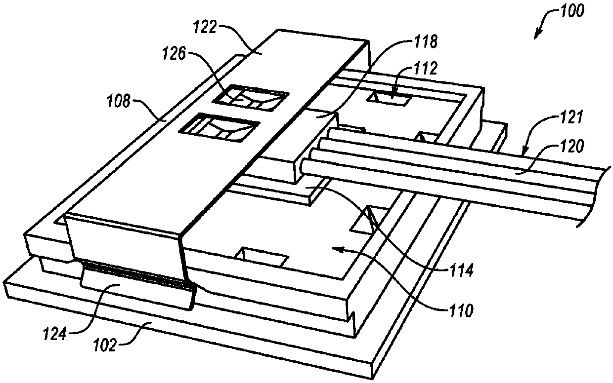
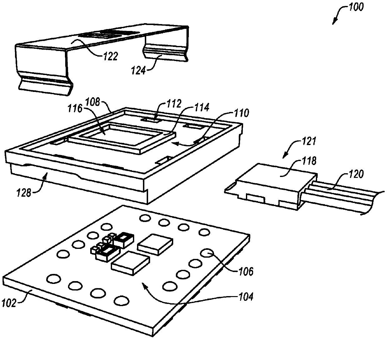
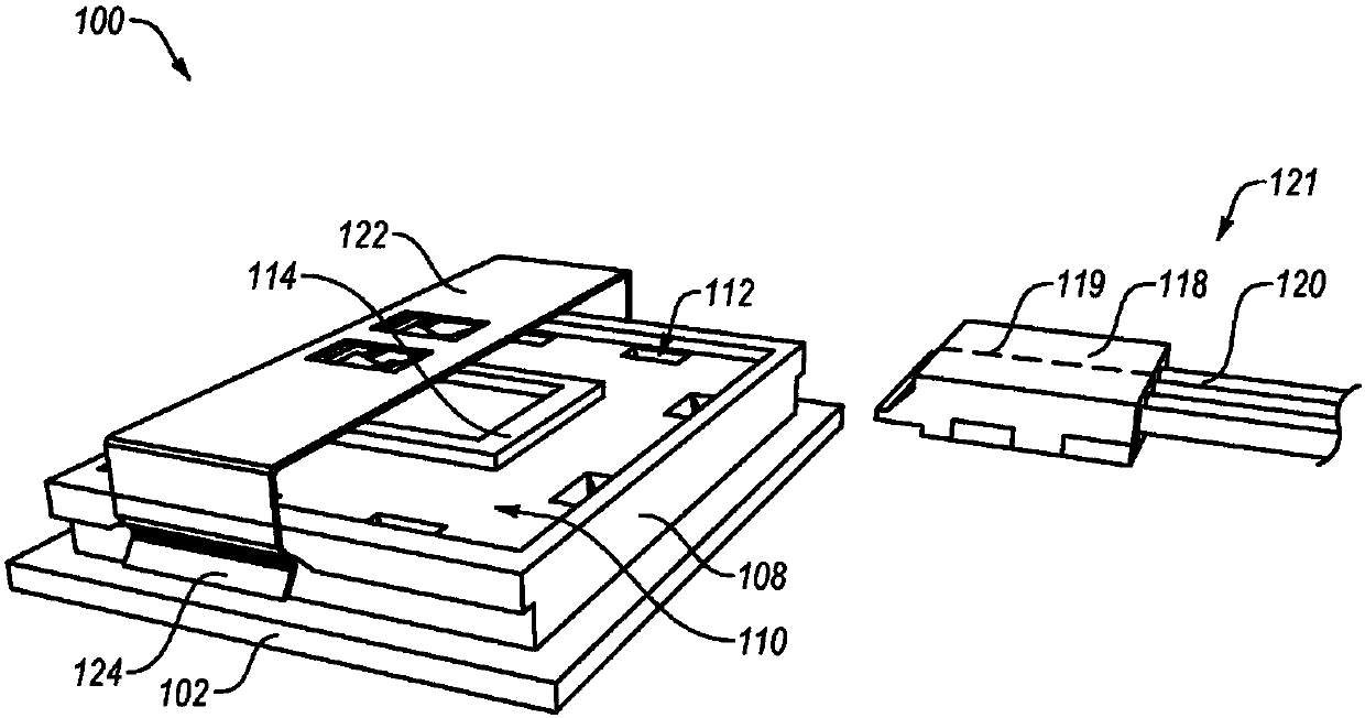
[0016] Embodiments described herein can facilitate high-precision alignment of optoelectronic and optical components without the need for robotic positioning systems or closed-loop feedback. Advantageously, embodiments can facilitate relatively accurate low-cost processes such as photolithographic metal patterning, plastic molding, etc. use together. Thus, for example, the final position of the part may be determined by the inherent accuracy of the most a...


PUM


Abstract

A system may include a substrate and a lens component. The substrate may include pads and solder protuberances. Each solder protuberance may be located on a pad. The lens component may define groovessized to receive at least a portion of the solder protuberances. The lens component may be positioned relative to the substrate such that at least a portion of each solder protuberance is positioned within the grooves. An optoelectronic transceiver comprises the system and a fiber optic cable including a cable lens component, a plurality of optical fibers at least partially positioned in the cablelens component, and a lens clip configured to be removably located on the transceiver lens component.

Description

[0001] Cross References to Related Applications [0002] This application claims U.S. Provisional Patent Application No. 62 / 195,877, filed July 23, 2015, entitled "COMPONENT ALIGNMENT" and U.S. Provisional Patent Application No. 62 / 237,817, the entire contents of both patent applications are hereby incorporated by reference. Background technique [0003] Precisely positioning the components of conventional optoelectronic devices relative to each other can be difficult. This is especially the case when doing so at high speed, at low cost, with tolerances in the low single digit micron (also micron or μm) range, for example in a mass production environment. As an example, high-speed lasers and photodetectors employed in optoelectronic devices may have small optical apertures, perhaps on the order of tens of microns. Alternatively or in addition, high bandwidth fibers may include comparable optical apertures. Furthermore, it is recommended that the lenses and mirrors used to d...

Claims


Application Information

Patent Timeline
Patent Type & Authority Applications(China)
IPC IPC(8): G02B6/42
CPCG02B6/4204G02B6/423G02B6/4238G02B6/4239G02B6/4249G02B6/4257G02B6/4244G02B6/428
Inventor 达林·詹姆斯·杜马弗兰克·弗伦斯
Owner FINISAR
Why Eureka
Try Eureka