Scalp clip

A scalp clip and splint technology, applied in the field of medical devices, can solve the problems of easily damaged scalp and inconvenient use of scalp clips

Active Publication Date: 2018-05-15
WUXI NO 2 PEOPLES HOSPITAL
View PDF9 Cites 2 Cited by
  • Summary
  • Abstract
  • Description
  • Claims
  • Application Information

AI Technical Summary

Problems solved by technology

[0003] Aiming at the above-mentioned problems, the present invention provides a scalp clip to solve the problems in the prior art that the scalp clip is inconvenient to use and easy to damage the scalp

Method used


Image

  • Scalp clip
  • Scalp clip
  • Scalp clip

Examples


Embodiment 1

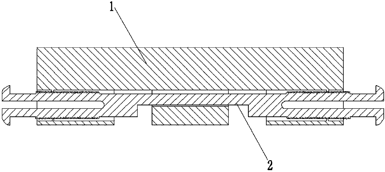
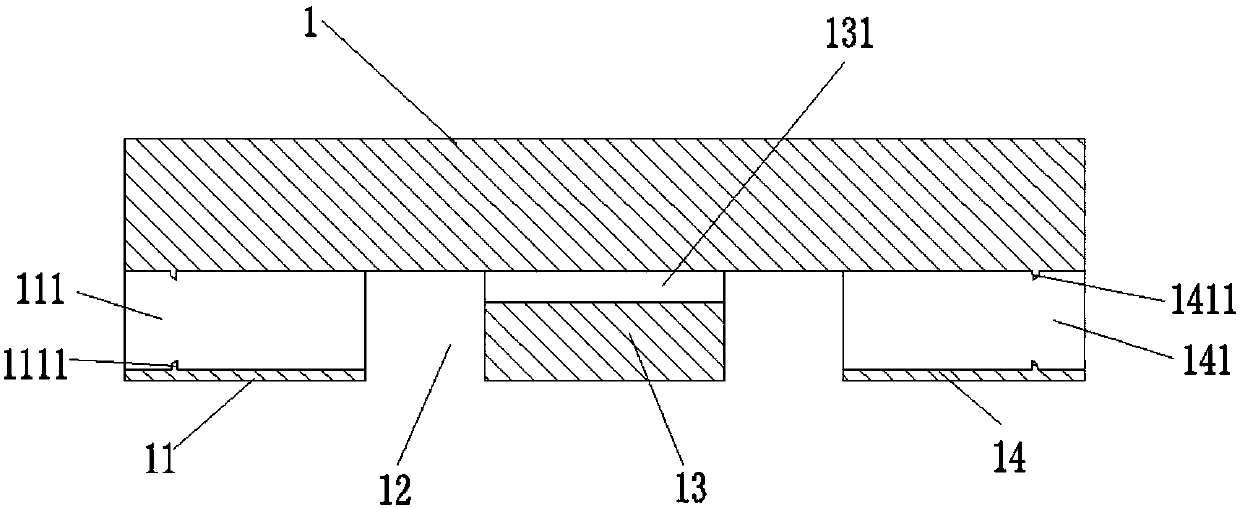
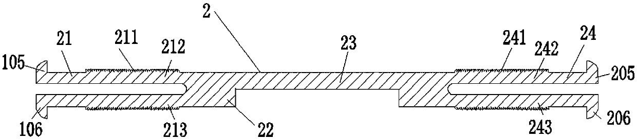
[0025] Such as Figure 1~3 , 7 to 8, the scalp wallet provided by Embodiment 1 of the present invention is characterized in that it includes: a base 1 and a pressing member 2; the base 1 includes a left fixing part 11, a left fixing gap, 12. The splint part 13 and the right fixing part 14; the left fixing part 11 is provided with a left through hole 111 pierced from left to right, and the right fixing part 14 is provided with a right through hole 141 pierced from left to right, and the splint part 13 is provided with a chute hole 131 pierced from left to right, the bottom of the chute hole 131 is higher than the left through hole 111, the inner wall of the left through hole 111 is provided with some left protrusions 1111, and the inner wall of the right through hole 141 There are several right protrusions 1411; the pressing part 2 includes a left pressing end 21, a clamping end 22, a sliding part 23 and a right pressing end 24; the left pressing end 21 is located in the left t...

Embodiment 2

[0034] Such as Figure 4-8 As shown, a scalp clip provided by Embodiment 2 of the present invention is characterized in that it includes: a base 1 and a pressing member 2; the base 1 includes a left fixing part 11, a left fixing gap 12, The splint part 13 and the right fixing part 14; the left fixing part 11 is provided with a left through hole 111 pierced from left to right, and the right fixing part 14 is provided with a right through hole 141 pierced from left to right. A chute hole 131 pierced from left to right is provided, the bottom of the chute hole 131 is higher than the left through hole 111, the inner wall of the left through hole 111 is provided with some left protrusions 1111, and the inner wall of the right through hole 141 is provided with Several right protrusions 1411; the pressing member 2 includes a left pressing end 21, a clamping end 22, a sliding part 23 and a right pressing end 24; the left pressing end 21 is located in the left through hole 111, and the...


PUM


Abstract

The invention provides a scalp clip. The scalp clip comprises a base and a pressing piece. The base comprises a left fixing portion, a left fixing gap, a clamping plate portion and a right fixing portion. A left through hole is formed in the left fixing portion, and a right through hole is formed in the right fixing portion. A sliding groove hole is formed in the clamping plate portion. The bottomof the sliding groove hole is higher than the left through hole. A left protrusion is arranged on the inner wall of the left through hole, and a right protrusion is arranged on the inner wall of theright through hole. The pressing piece comprises a left pressing end, a clamping end, a sliding portion and a right pressing end. The left pressing end is located in the left through hole. The slidingportion is located in the sliding groove hole. The right pressing end is located in the right through hole. The clamping end is located on the left side of the clamping plate portion. Left sawteeth are arranged on the outer wall of the left pressing end. Right sawteeth are arranged on the outer wall of the right pressing end. The left pressing end comprises a left upper arm and a left lower arm.The right pressing end comprises a right upper arm and a right lower arm. The scalp clip has the advantages that clamping force is changed through adjustment of the distance between the clamping end and the clamping plate portion, so that scalp injuries are avoided, and the scalp clip can be taken down or fastened conveniently even if the scalp swells.

Description

technical field [0001] The invention relates to the technical field of medical instruments, in particular to a scalp clip. Background technique [0002] When performing brain surgery, it is necessary to use scalp clips to fix the patient's cut scalp so that the scalp is hemostasis and fixed. The scalp clip in the prior art usually includes two clamping arms, one end of the two clamping arms is an opening close to each other, and the other end of the two clamping arms is connected by an elastic arc-shaped end. However, after the existing scalp clip clamps the scalp for a long time, the scalp tissue at the clamping part will edema and deform, causing the scalp clip to be difficult to remove, and even if it is removed, it will be difficult to fix the scalp again; The clamping strength of the clamp, the thicker the scalp, the greater the clamping force, which will lead to damage to the scalp, serious scalp infection, and endanger the safety of the patient's life. Contents of ...

Claims


Application Information

Patent Timeline
Patent Type & Authority Applications(China)
IPC IPC(8): A61B17/122
CPCA61B17/122A61B2017/12004
Inventor 马加威嵇丹丹罗亮
Owner WUXI NO 2 PEOPLES HOSPITAL
Why Eureka
Try Eureka