Air treatment device for metallurgical factory

A technology of air treatment device and air extraction device, which is applied in the direction of combination device, dispersed particle separation, chemical instrument and method, etc., can solve the problems of improper air treatment and so on

Inactive Publication Date: 2018-05-15
王森杰
View PDF6 Cites 5 Cited by
  • Summary
  • Abstract
  • Description
  • Claims
  • Application Information

AI Technical Summary

Problems solved by technology

[0005] In order to overcome the shortcoming that general metallurgical factories do not treat the air and affect the surrounding environment, the technical problem to be solved by the present invention is to provide an air treatment equipment for metallurgical factories that can process and discharge the air multiple times without affecting the surrounding environment. device

Method used


Image

  • Air treatment device for metallurgical factory
  • Air treatment device for metallurgical factory
  • Air treatment device for metallurgical factory

Examples


Embodiment 1

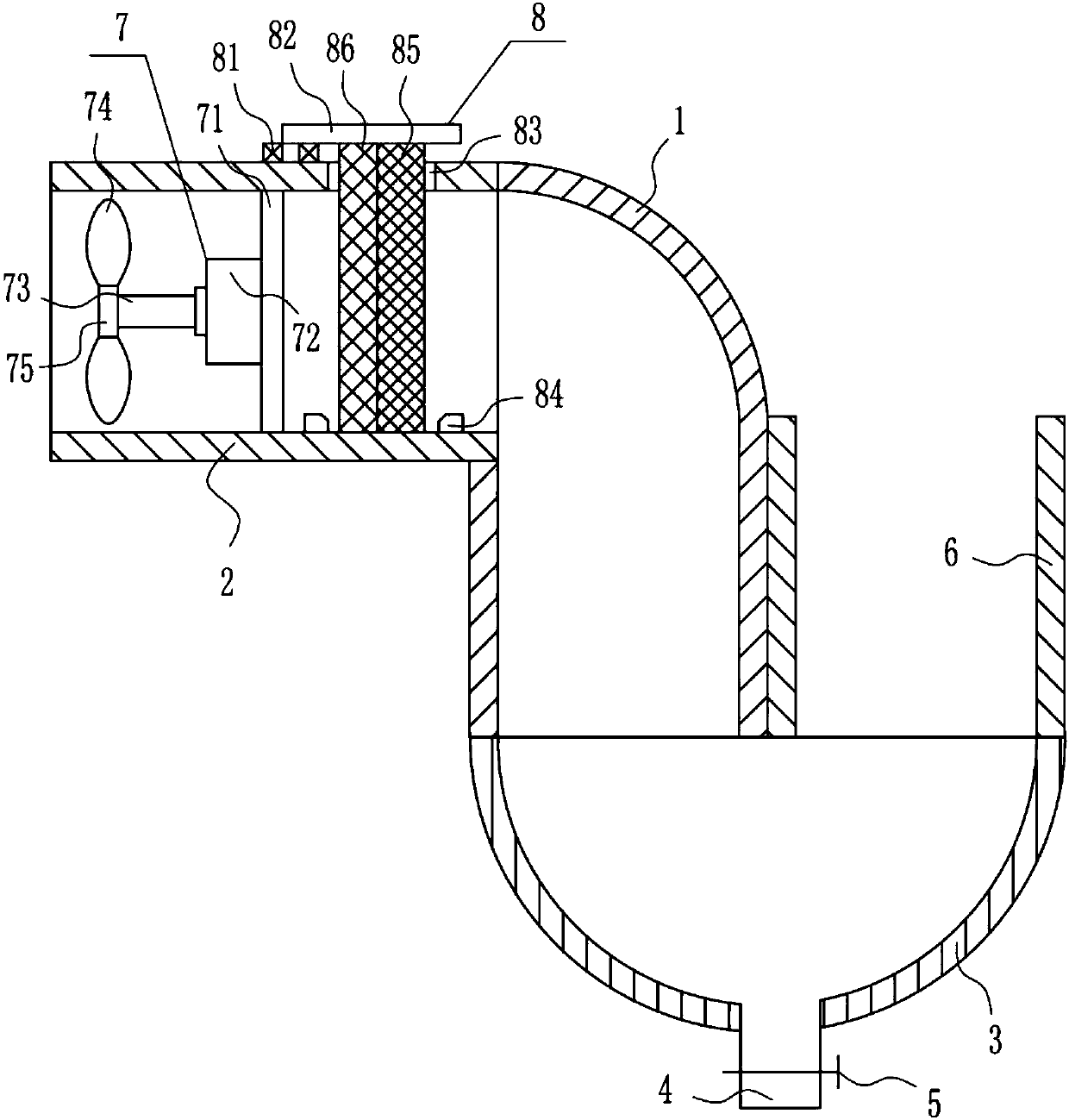
[0028] An air treatment device for a metallurgical plant, such as Figure 1-4 As shown, it includes an elbow 1, a pipeline 2, a hopper 3, a drain pipe 4, a valve 5, a pipe 6, an air extraction device 7 and a filter mechanism 8, the left side of the pipeline 2 is provided with an air extraction device 7, and the right side of the pipeline 2 There is a filter mechanism 8 on the side, the right end of the pipeline 2 is connected to the elbow 1, the elbow 1 is connected to the inside of the pipeline 2, the end of the elbow 1 is installed with a hopper 3, the hopper 3 is connected to the inside of the elbow 1, and the top of the hopper 3 is connected to the right side There is a pipe 6, which communicates with the inside of the hopper 3, the outer left side of the pipe 6 is connected with the lower part of the outer right side of the elbow 1, the middle of the bottom of the hopper 3 is connected with a drain pipe 4, the drain pipe 4 communicates with the inside of the hopper 3, and ...

Embodiment 2

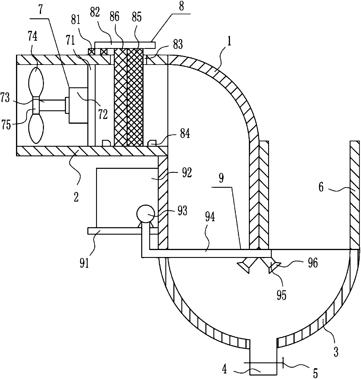
[0030] An air treatment device for a metallurgical plant, such as Figure 1-4 As shown, it includes an elbow 1, a pipeline 2, a hopper 3, a drain pipe 4, a valve 5, a pipe 6, an air extraction device 7 and a filter mechanism 8, the left side of the pipeline 2 is provided with an air extraction device 7, and the right side of the pipeline 2 There is a filter mechanism 8 on the side, the right end of the pipeline 2 is connected to the elbow 1, the elbow 1 is connected to the inside of the pipeline 2, the end of the elbow 1 is installed with a hopper 3, the hopper 3 is connected to the inside of the elbow 1, and the top of the hopper 3 is connected to the right side There is a pipe 6, which communicates with the inside of the hopper 3, the outer left side of the pipe 6 is connected with the lower part of the outer right side of the elbow 1, the middle of the bottom of the hopper 3 is connected with a drain pipe 4, the drain pipe 4 communicates with the inside of the hopper 3, and ...

Embodiment 3

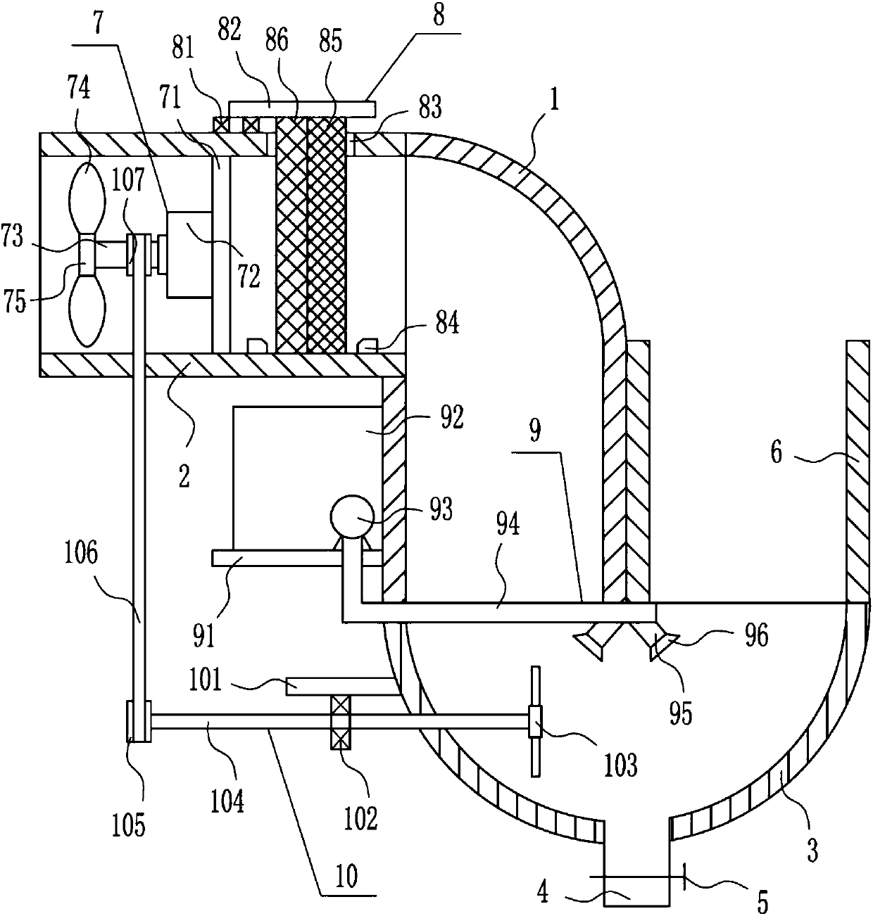
[0033] An air treatment device for a metallurgical plant, such as Figure 1-4 As shown, it includes an elbow 1, a pipeline 2, a hopper 3, a drain pipe 4, a valve 5, a pipe 6, an air extraction device 7 and a filter mechanism 8, the left side of the pipeline 2 is provided with an air extraction device 7, and the right side of the pipeline 2 There is a filter mechanism 8 on the side, the right end of the pipeline 2 is connected to the elbow 1, the elbow 1 is connected to the inside of the pipeline 2, the end of the elbow 1 is installed with a hopper 3, the hopper 3 is connected to the inside of the elbow 1, and the top of the hopper 3 is connected to the right side There is a pipe 6, which communicates with the inside of the hopper 3, the outer left side of the pipe 6 is connected with the lower part of the outer right side of the elbow 1, the middle of the bottom of the hopper 3 is connected with a drain pipe 4, the drain pipe 4 communicates with the inside of the hopper 3, and ...


PUM


Abstract

The invention relates to a treatment device, in particular to an air treatment device for a metallurgical factory, and aims to provide an air treatment device for the metallurgical factory, wherein the air treatment device can repeatedly treat and discharge air and cannot affect surrounding environments. In order to solve the technical problem, the air treatment device for the metallurgical factory comprises a bent pipe and the like. An air extractor is arranged on the inner left side of a pipeline, a filtering mechanism is arranged on the right inner side of the pipeline, the bent pipe is connected at the right end of the pipeline, the bent pipe is communicated with the inside of the pipeline, a hopper is mounted at the tail end of the bent pipe and communicated with the inside of the bent pipe, a pipe is connected with the right side of the top of the hopper and communicated with the inside of the hopper, and the outer left side surface of the pipe is connected with the lower portionof the outer right side of the bent pipe. According to the air treatment device, dust in the air can be removed, so that the air can be repeatedly treated and completely discharged, and the surrounding environments cannot be affected.

Description

technical field [0001] The invention relates to a treatment device, in particular to an air treatment device for a metallurgical plant. Background technique [0002] Metallurgy is the process and technology of extracting metals or metal compounds from minerals, and using various processing methods to make metals into metal materials with certain properties. [0003] In metallurgical factories, a large amount of air will be produced, and the air in metallurgy will affect the surrounding environment, and the air needs to be discharged after treatment. However, general metallurgical factories do not treat the air and affect the surrounding environment. Therefore, it is urgent to develop an energy An air treatment device for metallurgical plants that processes and discharges the air multiple times without affecting the surrounding environment. Contents of the invention [0004] (1) Technical problems to be solved [0005] In order to overcome the shortcoming that general met...

Claims


Application Information

Patent Timeline
Patent Type & Authority Applications(China)
IPC IPC(8): B01D50/00
CPCB01D50/60
Inventor 王森杰廖伟聪杜仕玲
Owner 王森杰
Why Eureka
Try Eureka