Snowfall simulating wind tunnel experiment device suitable for high fluidity particles
A wind tunnel experiment, high fluidity technology, applied in the direction of measuring device, aerodynamic test, machine/structural component test, etc., can solve the problems of high cost, achieve high simulation fidelity, simple device structure, stacking height maintain an even effect
- Summary
- Abstract
- Description
- Claims
- Application Information
AI Technical Summary
Problems solved by technology
Method used
Image
Examples
Embodiment 1
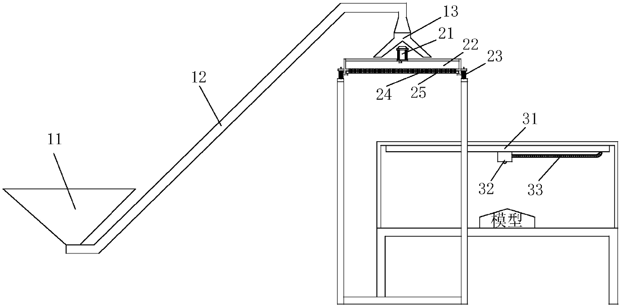
[0025] A wind tunnel experimental device suitable for simulating snowfall with high fluidity particles, suitable for wind tunnel tests with relatively large fluidity particles such as quartz sand, etc., its structure see figure 1 shown, including:
[0026] Feeding mechanism: used to transport the particles of simulated snowfall to the powder falling mechanism; the feeding mechanism includes a collection bucket 11, a feed pipe 12 and a distribution pipe 13, wherein the two ends of the feed pipe 12 are respectively connected to the collection bucket 11 and the distribution pipe 13. The material pipe 13 and the material distribution pipe 13 are placed above the powder falling pan 22 and are used to send the particles into the powder falling pan 22 .
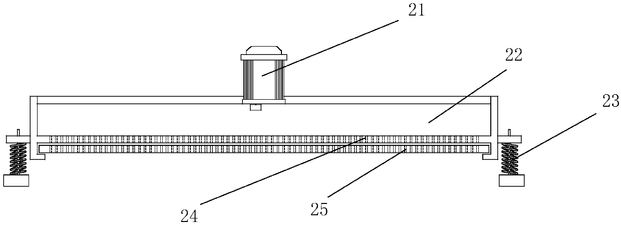
[0027] Powder falling mechanism: it consists of a bracket and a powder falling assembly arranged on the bracket. The powder falling assembly includes a powder falling frame, an upper bottom plate 24 and a lower bottom plate 25 which...
Embodiment 2
[0031] On the basis of embodiment 1, this embodiment is further set to:
[0032] Such as image 3 As shown, spring 23 is also installed between the powder falling frame and the support. The off-axis motor 21 that makes it vibrate is also installed on the powder falling frame. This kind of structure is suitable for the situation where the fluidity of the particles is relatively large. After the particles are sent to the powder dropping tray 22 by the feeding mechanism, the driving part is started to drive the lower bottom plate 25 to move, so that the powder falling of the upper bottom plate 24 and the lower bottom plate 25 that are staggered from each other The holes overlap to a certain extent, so that the particles fall from these staggered gaps. By changing the movement offset of the lower bottom plate 25, the falling flow of the particles can be controlled. During the powder falling process, the off-axis can also be started. The motor 21 makes the powder falling mechanis...
Embodiment 3
[0034] On the basis of embodiment 1, this embodiment is further set to:
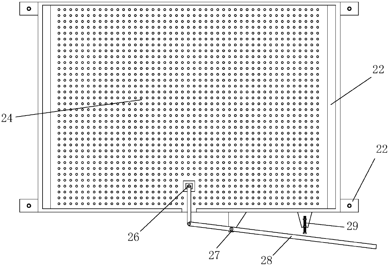
[0035] Such as image 3 As shown, the driver includes a connecting rod 26 and a push rod 28, wherein the two ends of the connecting rod 26 are respectively hinged to one end of the bottom plate 25 and the push rod 28, and the middle part of the push rod 28 is installed on the powder falling frame through a fulcrum bearing 27. The powder falling frame is also provided with a limit bolt 29. When the push rod 28 is pushed to pull the lower base plate 25, the limit bolt 29 resists the push rod 28 to limit the moving distance of the lower base plate 25. When the push rod 28 is pushed forward, the lower base plate 25 moves back a short distance, so that a gap appears in the hole between the upper base plate 24 and the lower base plate 25, and the particles fall from the gap, and the stop bolt 29 can be controlled by screwing in and out. The pushing amount of the push rod 28 controls the size of the gap, that ...
PUM
 Abstract
Description
Claims
Application Information
 - R&D
- Intellectual Property
- Life Sciences
- Materials
- Tech Scout
- Unparalleled Data Quality
- Higher Quality Content
- 60% Fewer Hallucinations
Browse by: Latest US Patents, China's latest patents, Technical Efficacy Thesaurus, Application Domain, Technology Topic, Popular Technical Reports.
© 2025 PatSnap. All rights reserved.Legal|Privacy policy|Modern Slavery Act Transparency Statement|Sitemap|About US| Contact US: help@patsnap.com


