
Backlight module and display device

A technology of backlight module and light source component, which is applied in the fields of reflection, display, diffraction, and backlight. It can solve problems such as poor display effect and uneven structural backlight, and achieve uniform light distribution, selectable, and uniform light output.

Active Publication Date: 2020-02-28
BOE TECH GRP CO LTD
View PDF4 Cites 0 Cited by
  • Summary
  • Abstract
  • Description
  • Claims
  • Application Information

AI Technical Summary

Problems solved by technology

[0003] The purpose of the present invention is to at least solve one of the above-mentioned technical defects, especially the problem of optical blind spots in the device structure that realizes single-side light output by means of optical waveguide coupling, and then solve the problem of uneven backlight of the structure, resulting in poor display effect.

Method used


Image

  • Backlight module and display device
  • Backlight module and display device
  • Backlight module and display device

Examples


Embodiment 1

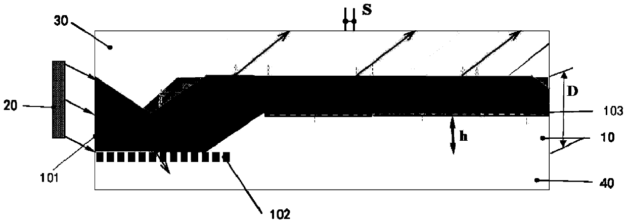
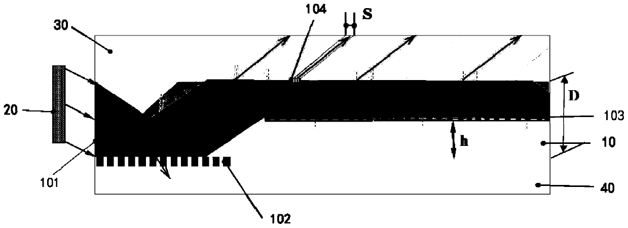
[0044] refer to figure 1 In one embodiment, the present invention provides that the light emitted by the light source assembly 20 enters the waveguide layer 10 through the light incident surface 101 at a preset angle, and then enters the waveguide layer 10 from the waveguide layer 10 The angle of the first grating layer 102 is the incident angle, the length of the first grating layer 102 is the product of the thickness of the waveguide layer 10 and the tangent of the incident angle, and the first grating layer 102 is close to the incident angle One end of the light surface 101 is flush with the light incident surface 101 . The length of the first grating layer 102 is the thickness of the waveguide layer 10 and the incident angle θ i The product of tangent values.

[0045] Specifically:

[0046] c=D×tanθ i

[0047] c is the length of the first grating layer 102, D is the thickness of the waveguide layer, θ i is the incident angle, the incident light can all be incident on...

Embodiment 2

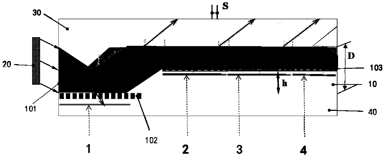
[0060] Such as Figure 4 As shown, in one embodiment, the present invention provides that the length of the first grating layer 102 is equal to the length of the waveguide layer 10, and the second grating layer 103 includes a plurality of grating groups 1031 arranged at intervals, The radiation area of ​​each reflection of light at the light exit surface corresponds to one of the grating groups 1031, and one end of each grating group 1031 close to the light incident surface 101 is located at the corresponding periodic reflected light area close to the light incident surface 101 the edge of.

[0061] The first grating layer 102 is composed of a plurality of reflective grating components, and the second grating layer 103 is composed of a plurality of transmissive grating components. The first grating layer 102 and the second grating layer 103 can diffract light out of the light exit surface of the waveguide layer 10, and can enter the upper substrate 30 from the light exit surf...


PUM

PropertyMeasurementUnit
thicknessaaaaaaaaaa
thicknessaaaaaaaaaa

Abstract

The invention provides a backlight module. The module comprises a waveguide layer and a light source assembly, the waveguide layer comprises an incident surface located on the side surface of the waveguide layer, a bottom surface positioned at the bottom of the waveguide layer and a light emitting surface positioned at the top of the waveguide layer, wherein a first grating layer is arranged on the bottom surface, and a second grating layer is further arranged inside the waveguide layer; light emitted by the light source assembly enters the waveguide layer through the light incident surface ata preset angle and is transmitted to the first grating layer and the bottom surface, the light transmitted to the first grating layer is diffracted by the first grating layer to the light emitting surface and is emitted from the light emitting surface, the light transmitted to the bottom surface is reflected to the light emitting surface through the bottom surface and is reflected to the second grating layer at the light emitting surface, light reflected to the second grating layer at the light emitting surface is diffracted by the second grating layer to the light emitting surface and is emitted from the light emitting surface. According to the backlight module, the uniform and countinuous light emitting of the whole surface of the backlight component is realized, the light energy of thewhole light emitting surface is uniformly distributed, and meanwhile, the selectivity of the light emitting direction is realized, so that the purpose of single-side light emitting is achieved.

Description

technical field [0001] The present invention relates to the technical field of backlight, diffraction, reflection and display, in particular, the present invention relates to a backlight module and a display device. Background technique [0002] In the current market, the side-entry collimated single-side front backlight is the most widely used backlight method with great application value. It means that the light source guides the light evenly along the electronic ink screen or LCD screen from top to bottom, so that the light emitted by the light source will not directly shine on the eyes. It has a high sense of comfort, so the front backlight technology is widely used in display devices such as electronic paper books. However, at present, the device structure that achieves one-sided light output through optical waveguide coupling will have an optical blind zone, that is, no light is emitted in some middle areas of the light output surface, resulting in uneven backlighting...

Claims


Application Information

Patent Timeline
Patent Type & Authority Patents(China)
IPC IPC(8): F21S8/00F21V8/00G02B5/18G02B6/00G02F1/13357
CPCF21S8/00F21V2200/00G02B5/1861G02B6/005G02F1/133606
Inventor 孟宪东王维孟宪芹谭纪风陈小川杨亚锋高健
Owner BOE TECH GRP CO LTD
Learn More