Clamping type pipe bending equipment

A clip-on, pipe fitting technology, used in metal processing equipment, feeding devices, positioning devices, etc., can solve the problems of difficult pipe bending, laborious operation, and long time consumption, so as to increase friction and buffer friction. Effect

Inactive Publication Date: 2018-05-22
ANHUI TECHN COLLEGE OF MECHANICAL & ELECTRICAL ENG
View PDF6 Cites 9 Cited by
  • Summary
  • Abstract
  • Description
  • Claims
  • Application Information

AI Technical Summary

Problems solved by technology

[0002] In mechanical production work and on-site construction work, plumbing pipes and various plastic pipes often need to be bent when they are used. At present, when performing pipe bending operations, bending pipe springs are generally used, and the staff need to extend the bending pipe springs into the pipe fittings In the process of bending pipe fittings by external force, the operation is laborious, and it is often necessary to bend multiple pipe fittings during construction. Such an operation method makes the bending operation take a long time, and the bending range is The operating angle of each bending is difficult to be the same and it is difficult to obtain precise control. Now a device for group bending is needed to solve the above problems and improve the efficiency and precision of bending

Method used


Image

  • Clamping type pipe bending equipment
  • Clamping type pipe bending equipment
  • Clamping type pipe bending equipment

Examples


Embodiment Construction

[0017] The following will clearly and completely describe the technical solutions in the embodiments of the present invention with reference to the accompanying drawings in the embodiments of the present invention. Obviously, the described embodiments are only some, not all, embodiments of the present invention. Based on the embodiments of the present invention, all other embodiments obtained by persons of ordinary skill in the art without making creative efforts belong to the protection scope of the present invention.

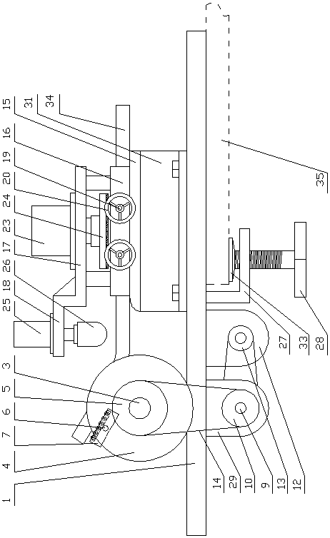
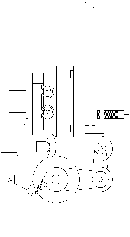
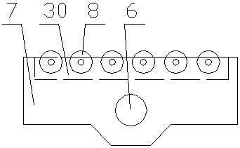
[0018] see Figure 1-6 , the present invention provides a technical solution: a clamp-type pipe fitting bending equipment, including a main frame 1 of the device, a main shaft seat 2 is welded on the upper part of the main frame 1 of the device, and the main shaft seat 2 is rotatably matched with the main shaft 3, The key on the main shaft 3 is connected with a runner 4 and a driven sprocket 5, and the runner 4 is connected with a push shaft 6, and the push sh...


PUM


Abstract

The invention discloses clamping type pipe bending equipment. The equipment comprises a device main frame; a spindle base is welded to the upper part of the device main frame and is matched with the spindle in a rotating mode; a rotating wheel and a driven chain wheel are connected to the spindle in a key mode; a push shaft is connected to the rotating wheel; a pipe push support is arranged on thepush shaft in a rotating mode; the driven chain wheel is matched with transfer chain wheels on a transfer shaft; a supporting plate frame is further detachably connected to the device main frame; supporting frames are welded to the two sides of the upper part of the supporting plate frame; a top plate frame is connected to the upper parts of the supporting frames; a lower pressing plate frame iswelded to one end of the top plate frame; a plurality of limiting bolts are connected to the supporting frames in a screwed mode; a fixed oil cylinder is arranged on the top plate frame; a lower pressing oil cylinder is arranged on the lower pressing plate frame; a right-angled frame is welded to the lower part of the device main frame; and a clamping bolt is connected to the right-angled frame ina screwed mode. The clamping type pipe bending equipment is clamped on a workbench, pipes can be bent in batches, the working efficiency is high, the uniformity of the bending angles of the pipes isgood, the operation is labor-saving and simple, and the application range is wide.

Description

technical field [0001] The invention relates to the field of bending equipment, in particular to a clip-on bending equipment for pipe fittings. Background technique [0002] In mechanical production work and on-site construction work, plumbing pipes and various plastic pipes often need to be bent when they are used. At present, when performing pipe bending operations, bending pipe springs are generally used, and the staff need to extend the bending pipe springs into the pipe fittings In the process of bending pipe fittings by external force, the operation is laborious, and it is often necessary to bend multiple pipe fittings during construction. Such an operation method makes the bending operation take a long time, and the bending range is The operating angle of each bending is difficult to be the same and it is difficult to obtain precise control. Now a device for bending pipes in groups is needed to solve the above problems and improve the efficiency and precision of pipe ...

Claims


Application Information

Patent Timeline
Patent Type & Authority Applications(China)
IPC IPC(8): B21D7/06B21D7/024B21D43/00B29C53/08B29C53/80
CPCB21D7/06B21D7/024B21D43/003B29C53/083B29C53/80
Inventor 阚玉锦马开帅李奇
Owner ANHUI TECHN COLLEGE OF MECHANICAL & ELECTRICAL ENG
Why Eureka
Try Eureka