Supercharge Your Innovation With Domain-Expert AI Agents!

Flexible adhesive tearing mechanism

A flexible and flexible body technology, applied in the field of flexible glue tearing mechanism, can solve problems such as damage to the workpiece, and achieve the effect of preventing stress concentration at the tearing place

Pending Publication Date: 2018-05-22
SHENZHEN HYMSON LASER INTELLIGENT EQUIP CO LTD
View PDF11 Cites 4 Cited by
  • Summary
  • Abstract
  • Description
  • Claims
  • Application Information

AI Technical Summary

Problems solved by technology

[0004] The invention aims to solve the technical problem that the prior art tearing glue mechanism easily leads to stress concentration at the glue tearing place of the workpiece, thereby causing damage to the workpiece. Self-adjustment during the process to prevent stress concentration at the glue tearing place of thin plate workpieces when the mechanism is tearing glue, causing damage to the workpiece

Method used


Image

  • Flexible adhesive tearing mechanism
  • Flexible adhesive tearing mechanism
  • Flexible adhesive tearing mechanism

Examples


Embodiment Construction

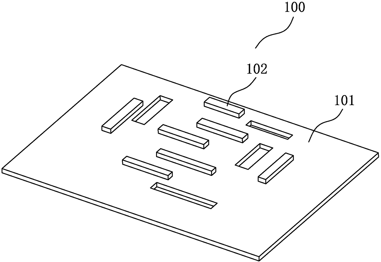
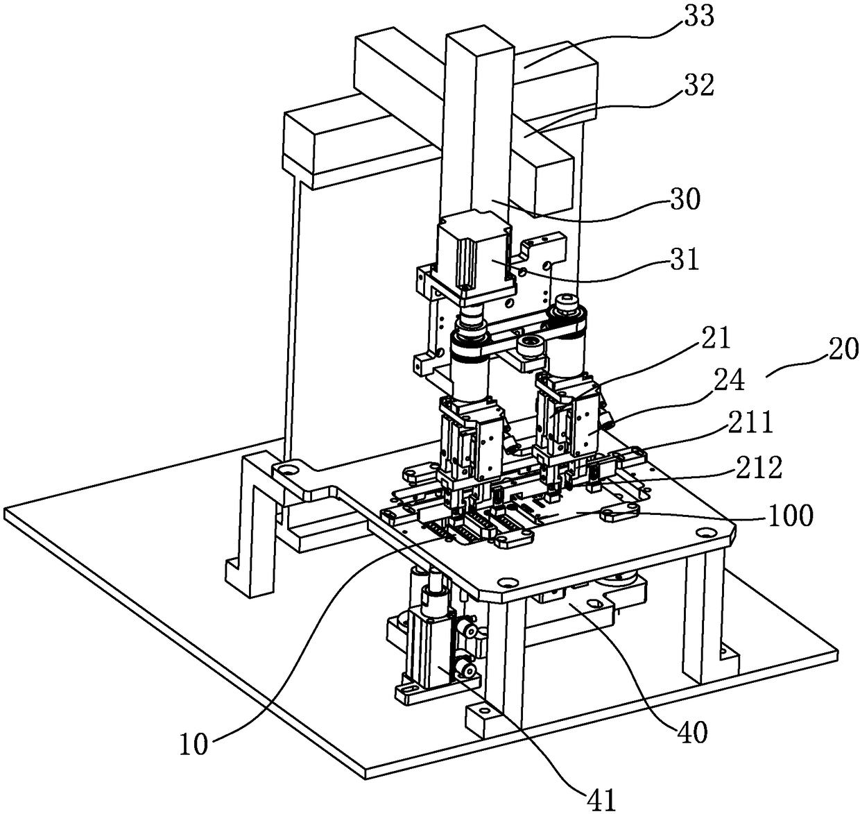
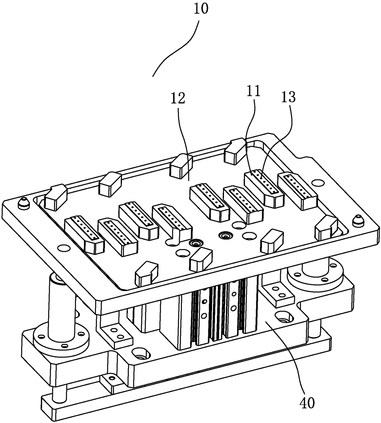
[0024] Refer to the following Figure 1 to Figure 5 , the present invention is described in detail. It should be pointed out that the present invention can be implemented in many different ways and is not limited to the embodiments described herein. On the contrary, the purpose of providing these embodiments is to enable those skilled in the art to understand more thoroughly the content disclosed in the present invention comprehensive.

[0025] Furthermore, the description of illustrative embodiments in accordance with the principles of this invention is intended to be read in conjunction with the accompanying drawings, which are to be considered a part of this entire written description. In the description of the disclosed embodiments of the invention, reference to any direction or orientation is for convenience of illustration only and is not intended to limit the scope of the invention in any way. Related terms such as "X-axis", "Y-axis", and "Z-axis" should be interprete...


PUM


Abstract

The invention discloses a flexible adhesive tearing mechanism used for tearing adhesive from sheet type workpieces. The mechanism comprises a workpiece placing portion, an adhesive tearing portion anda first mechanical hand. The sheet type workpieces are placed on the workpiece placing portion, the adhesive tearing portion is provided with an adhesive tearing clamping jaw for tearing adhesive from the sheet type workpieces, and the output end of the first mechanical hand is connected with the adhesive tearing portion to drive the adhesive tearing portion to be close to or away from the sheettype workpieces so that the adhesive tearing clamping jaw can tear adhesive from the sheet type workpieces. The adhesive tearing portion further comprises a first flexible body capable of being deformed in the driving direction of the first mechanical hand and a sliding portion capable of sliding in the driving direction of the first mechanical hand. The adhesive tearing clamping jaw is installedon the sliding portion and connected with the first flexible portion. According to the flexible adhesive tearing mechanism, self adjustment in the adhesive tearing process can be achieved, and the problem that the workpieces are damaged due to stress concentration at the adhesive tearing positions of the sheet type workpieces when the mechanism tears adhesive is prevented.

Description

technical field [0001] The invention relates to a device or method for manufacturing printed circuits, in particular to a flexible adhesive tearing mechanism. Background technique [0002] For thin-plate workpieces such as plastic panels, display screens, PCB boards, and FPC boards, when coating the surface, the electronic components on it do not require coating, so plastic panels, display screens, PCB boards, and FPC boards need to be coated. The electronic components on the board and so on are wrapped with tape or glued first, and the tape or glue needs to be torn off after the coating and other treatments are completed. [0003] In the prior art, the plastic tearing mechanism of the rubber tearing jaws driven by a manipulator is usually used to tear glue from thin plate workpieces such as plastic panels, display screens, PCB boards, and FPC boards. It cannot be adjusted automatically during the gluing process, and the plastic panels, display screens, PCB boards, FPC boar...

Claims


Application Information

Patent Timeline
Patent Type & Authority Applications(China)
IPC IPC(8): B65B69/00
CPCB65B69/00
Inventor 田亮刘明清汪结顺钟辉黄世生詹义勇周宇超林国栋张松岭
Owner SHENZHEN HYMSON LASER INTELLIGENT EQUIP CO LTD
Features
  • R&D
  • Intellectual Property
  • Life Sciences
  • Materials
  • Tech Scout
  • Unparalleled Data Quality
  • Higher Quality Content
  • 60% Fewer Hallucinations
Learn More