Differential circuit, capacitance detecting circuit, touch detecting device and terminal equipment

A differential circuit and capacitance detection technology, which is applied in the electronic field, can solve problems such as large self-capacitance, reduced sensitivity, and the inability to integrate cancel capacitors.

Active Publication Date: 2018-05-22
SHENZHEN GOODIX TECH CO LTD
View PDF5 Cites 25 Cited by
  • Summary
  • Abstract
  • Description
  • Claims
  • Application Information

AI Technical Summary

Problems solved by technology

[0003] However, since the self-capacitance is often relatively large, the existing self-capacitance detection method has low sensitivity when the self-capacitance is large; and the cancel capacitor used to improve the sensitivity is large, so that the cancel capacitor cannot be integrated, and the cost of the cancel capacitor It is also too high; further, the increase of self-capacitance reduces the sensitivity of the existing self-capacitance detection method, and it is no longer possible to correctly detect the capacitance value
[0004] Using a differential circuit can improve the sensitivity of capacitance detection to a certain extent, but there are often noise signals such as 1 / noise and low-frequency noise, which affect the signal-to-noise ratio of the output signal. Therefore, a low-noise differential circuit is urgently needed

Method used


Image

  • Differential circuit, capacitance detecting circuit, touch detecting device and terminal equipment
  • Differential circuit, capacitance detecting circuit, touch detecting device and terminal equipment
  • Differential circuit, capacitance detecting circuit, touch detecting device and terminal equipment

Examples


Embodiment Construction

[0065] The technical solutions in the embodiments of the present application will be described below with reference to the accompanying drawings.

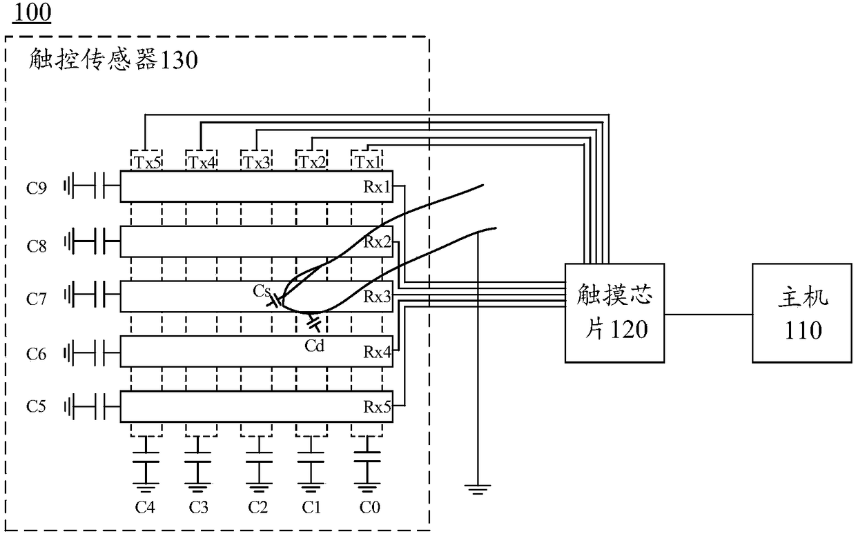
[0066] For ease of understanding, the following combination figure 1 A schematic diagram describing a possible application scenario of the differential circuit in the embodiment of the present application.

[0067] figure 1 A capacitive touch system 100 is shown, and the capacitive touch system 100 includes a host (Host) 110 , a touch integrated circuit (Touch IC) 120 and a touch sensor 130 . Wherein, the touch sensor 130 includes a Tx layer and an Rx layer, the Tx layer includes Tx1 channel, Tx2 channel, Tx3 channel, Tx4 channel and Tx5 channel, and the Rx layer includes Rx1 channel, Rx2 channel, Rx3 channel, Rx4 channel, Rx5 channel. In the Tx layer, the ground capacitances of the Tx1 channel, Tx2 channel, Tx3 channel, Tx4 channel, and Tx5 channel are C0, C1, C2, C3, and C4 respectively; in the Rx layer, the Rx1 channel, Rx2 ch...


PUM


Abstract

The application provides a differential circuit, a capacitance detecting circuit and a touch detecting device, which can reduce the noise of the differential circuit and improve the signal-to-noise ratio of an output signal. When the differential circuit is applied to the capacitance detecting circuit, the accuracy of the capacitance detection can be improved. The differential circuit comprises afront end circuit and a processing circuit, wherein the front end circuit comprises a control circuit and a PGA circuit, the control circuit is connected to a power supply, two capacitors, and a PGA circuit for controlling the power supply to charge the two capacitors and controlling the two capacitors to discharge to the PGA circuit in a first stage, and for controlling the PGA circuit to chargetwo capacitors in the second stage; the PGA circuit is used for converting the capacitance signals of the two capacitors into voltage signals and obtain the difference in the first and second stages,in order to obtain a differential signal corresponding to the voltage of two capacitors in the first and second stages; the processing circuit is connected to the front end circuit for determining a target differential signal of the voltage corresponding to the two capacitors according to the differential signal output by the front end circuit in the first and second stages.

Description

technical field [0001] The present application relates to the field of electronic technology, and in particular to a differential circuit, a capacitance detection circuit, a touch detection device and a terminal device. Background technique [0002] Capacitors are widely used in many terminal electronic devices, for example, touch sensors for touch control on terminal device display screens. During the use of capacitors, it is essential to measure and analyze their capacitance value. Nowadays, self-capacitance detection has become a very important measurement and analysis method. [0003] However, since the self-capacitance is often relatively large, the existing self-capacitance detection method has low sensitivity when the self-capacitance is large; and the cancel capacitor used to improve the sensitivity is large, so that the cancel capacitor cannot be integrated, and the cost of the cancel capacitor Furthermore, the increase of the self-capacitance reduces the sensitivi...

Claims


Application Information

Patent Timeline
Patent Type & Authority Applications(China)
IPC IPC(8): G01R27/26
CPCG01R27/26G01R27/2605G06F3/0416G06F3/044G06F3/04166G06F3/04182G06F3/0446G06F3/0418
Inventor 蒋宏袁广凯
Owner SHENZHEN GOODIX TECH CO LTD
Why Eureka
Try Eureka