
Injection device

A technology for injection devices and shells, which can be used in the direction of syringes, medical equipment, infusion sets, etc., and can solve the problems of poor user feeling, adjustment structure and setting methods that do not use user observation, etc.

Pending Publication Date: 2018-05-25
JIANGSU WANHAI MEDICAL INSTR CO LTD
View PDF0 Cites 2 Cited by
  • Summary
  • Abstract
  • Description
  • Claims
  • Application Information

AI Technical Summary

Problems solved by technology

[0004] The purpose of the present invention is to provide an injection device to improve the technical problems in the prior art that the setting method of the adjustment structure does not use the user to observe, and the use feeling is poor

Method used


Image

  • Injection device
  • Injection device
  • Injection device

Examples


Embodiment Construction

[0024] The technical solutions of the present invention will be clearly and completely described below with reference to the accompanying drawings. Obviously, the described embodiments are a part of the embodiments of the present invention, but not all of the embodiments. Based on the embodiments of the present invention, all other embodiments obtained by those of ordinary skill in the art without creative efforts shall fall within the protection scope of the present invention.

[0025] In the description of the present invention, it should be noted that when the terms "center", "upper", "lower", "left", "right", "vertical", "horizontal", "inner", "outer" appear. ”, etc., the indicated orientation or positional relationship is based on the orientation or positional relationship shown in the accompanying drawings, only for the convenience of describing the present invention and simplifying the description, rather than indicating or implying that the indicated device or element m...


PUM


Abstract

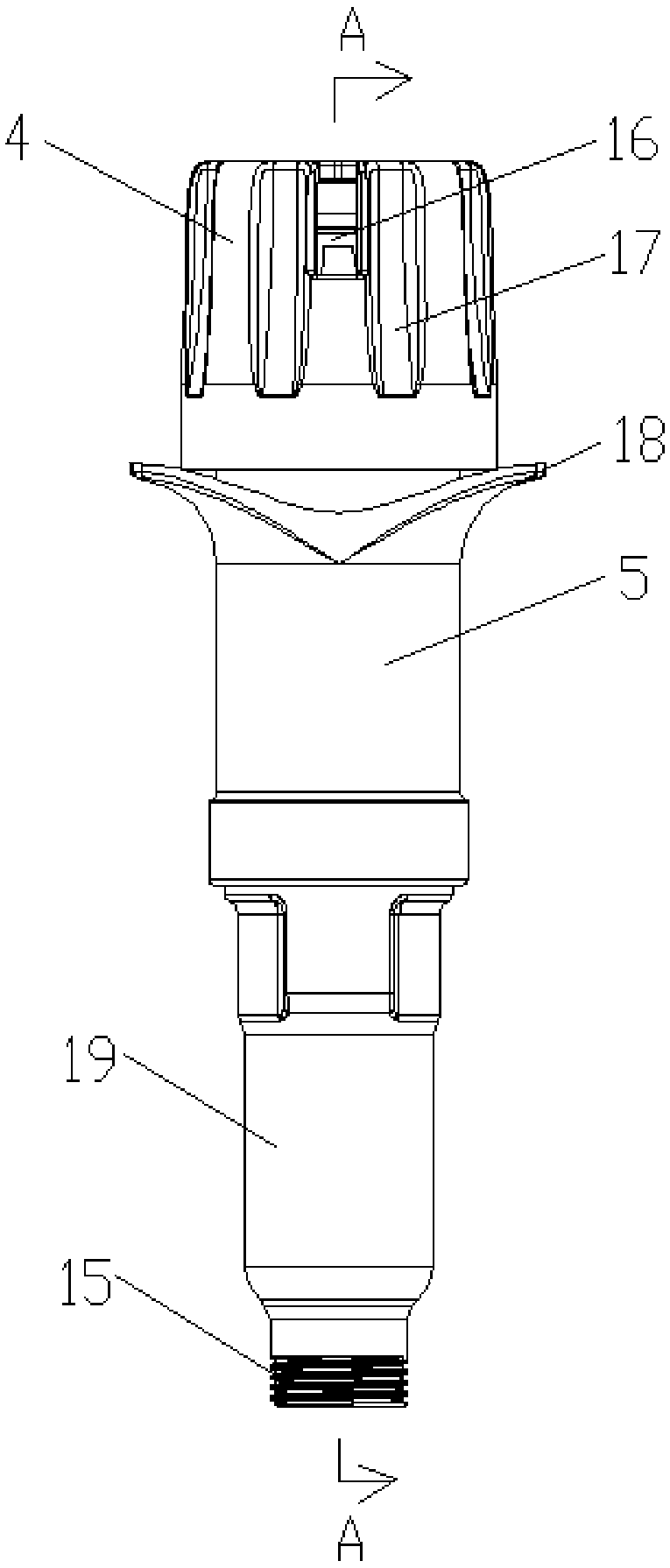
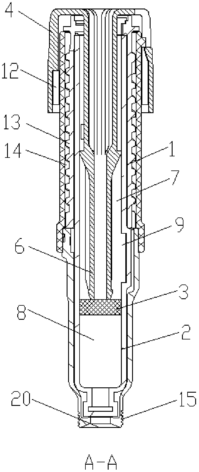
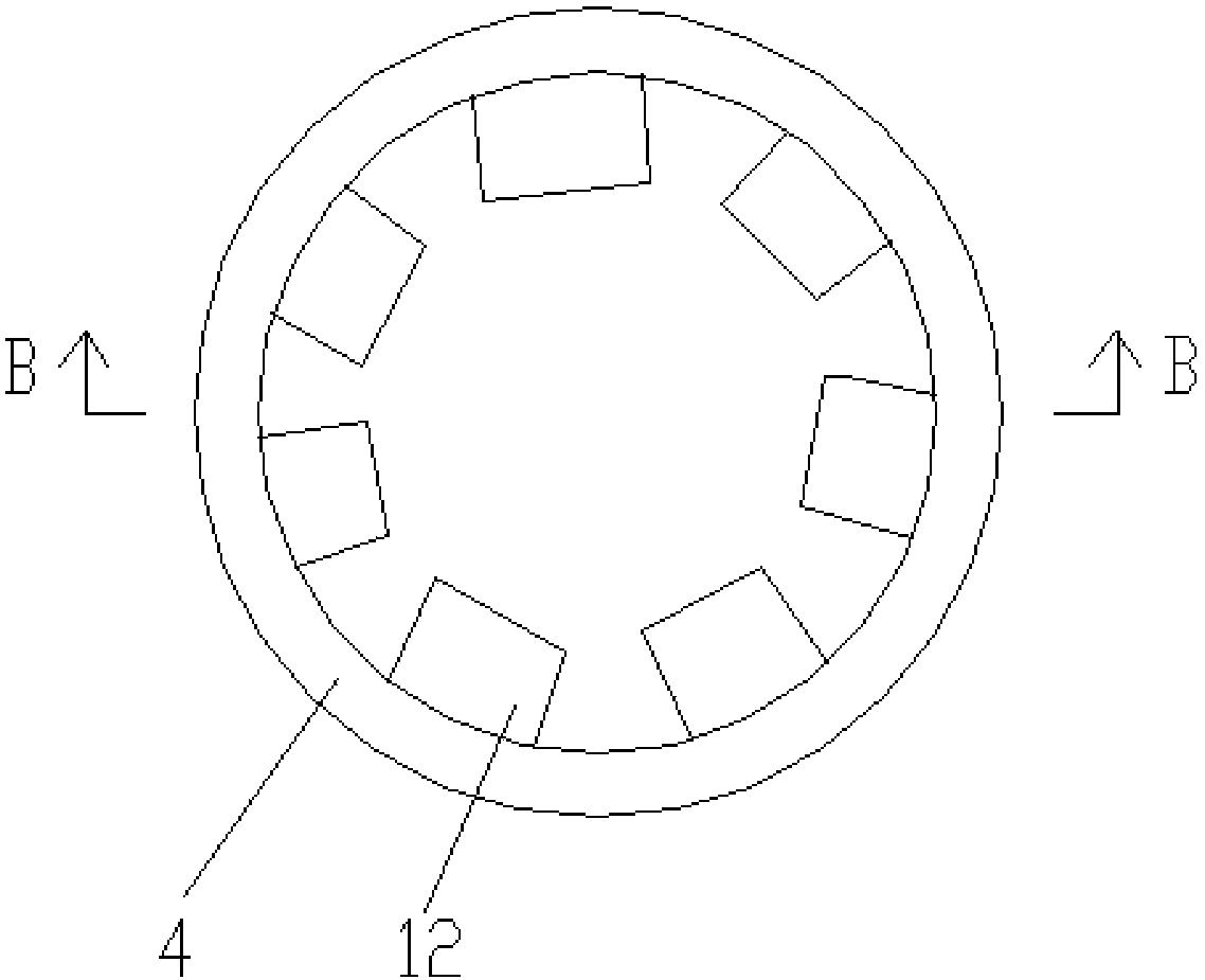
The invention provides an injection device and relates to the technical field of medical equipment. The injection device comprises an extrusion part, an end cap, an adjustment housing and a push rod;one end of the extrusion part is used for abutting against a piston and used for moving up and down along the inner wall of a mixing housing; the adjustment housing sleeves the upper end of the outside of the extrusion part; the outer wall of the adjustment housing is provided with a bump; one end of the adjustment housing far away from the extrusion part is provided with a through hole for the push rod to pass through; the inner wall of the end cap is provided with a scale groove matched with the bump, and the scale groove extends in the axial direction of the end cap. The scale groove and the bump are disposed at the top of the device, which can facilitate a user's observation and enables the touch to be good.

Description

technical field [0001] The present invention relates to the technical field of medical equipment, in particular to an injection device. Background technique [0002] Some medicines have a shorter shelf life in liquid state and longer shelf life in solid powder state. In order to prolong the shelf life of the drug, a removable and replaceable mixing housing and piston are usually built into the interior of the injection device. The piston is arranged inside the mixing shell, and divides the inside of the mixing shell into a sealed upper cavity and a lower cavity with the same inner diameter. The piston can move up and down along the inner wall of the mixing shell; the upper cavity is provided with water, and the lower cavity is provided with water. The medicine powder is arranged in the middle; the side wall of the lower cavity is provided with a convex part cavity, when the injection device pushes the piston to move to the convex part cavity, the upper cavity and the lower ...

Claims


Application Information

Patent Timeline
IPC IPC(8): A61M5/19A61M5/31
CPCA61M5/19A61M5/31A61M2005/3126A61M2205/19
Inventor 罗来荣
Owner JIANGSU WANHAI MEDICAL INSTR CO LTD
Learn More