Positioning tool for engine inspection

A technology for positioning tooling and engines, which is applied in the direction of engine testing, measuring devices, and testing of machine/structural components, etc. It can solve the problems of difficult engine operation, reduce manual labor, facilitate operation, and save power resources.

Active Publication Date: 2019-07-23
泾县凡泽科技服务有限公司
View PDF5 Cites 0 Cited by
  • Summary
  • Abstract
  • Description
  • Claims
  • Application Information

AI Technical Summary

Problems solved by technology

[0005] The present invention intends to provide a positioning tool for engine inspection to solve the problem of relatively difficult operation in engine inspection in the prior art

Method used


Image

  • Positioning tool for engine inspection
  • Positioning tool for engine inspection
  • Positioning tool for engine inspection

Examples


Embodiment Construction

[0023] The following is further described in detail through specific implementation methods:

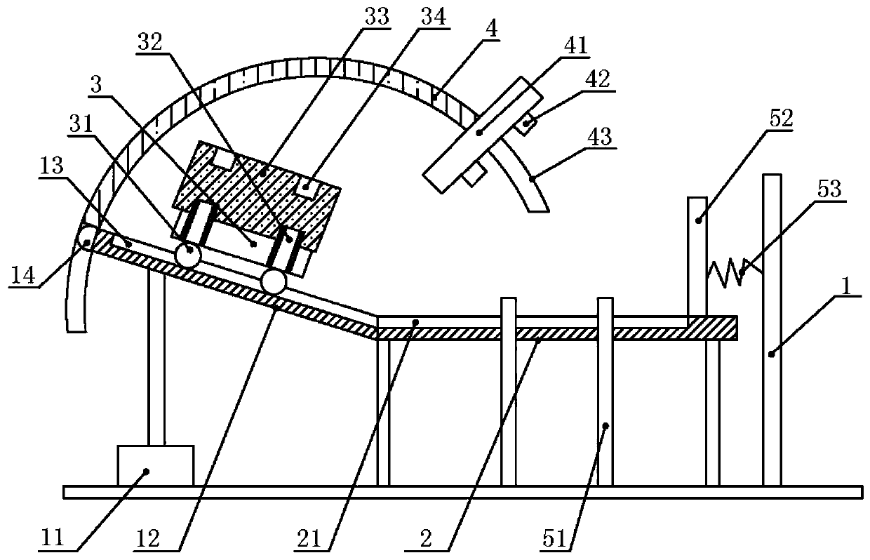
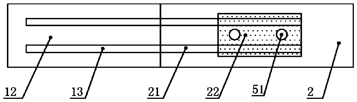
[0024] The reference signs in the accompanying drawings of the description include: frame 1, cylinder 11, slide table 12, second slide rail 13, ball 14, support table 2, first slide rail 21, turning plate 22, loading cart 3, rollers 31, positioning pipe 32, motor 33, mounting hole 34, pole 4, pressing plate 41, positioning pin 42, slideway 43, positioning column 51, baffle plate 52, spring 53.

[0025] Such as figure 1 As shown, the positioning tool for engine detection of the present invention includes a frame 1, and a supporting platform 2 is installed on the frame 1, such as figure 2 As shown, the support platform 2 is provided with a parallel first slide rail 21, the middle part of the support platform 2 is provided with an opening, and a flap 22 is installed at the opening, and the edge of the flap 22 is connected with the edge of the opening by glue. A first slide rail 21 is...


PUM


Abstract

The invention relates to a workpiece positioning device, specifically a positioning tool for engine detection. The tool comprises a supporting platform, and the supporting platform is provided with afirst sliding rail. One side of the supporting platform is hinged to a sliding table, and the sliding table is provided with a second sliding rail. The first sliding rail and the second sliding rail are connected with each other, and a material carrying vehicle is disposed above the sliding table and is provided with a positioning tube. The positioning tube vertically passes through the material carrying vehicle, and one end of the positioning tube extends above the material carrying tube. The bottom of the material carrying vehicle is provided with a roller, and the roller is slidingly connected with the first sliding rail and the second sliding rail. A chute is disposed above the sliding table, and the interior of the chute is slidingly provided with a supporting rod. One end of the supporting rod is connected with a pressing plate, the bottom of the pressing plate is provided with a positioning pin, and the other end of the supporting rod abuts against the free end of the sliding table. The sliding table is slidingly connected with the chute. The tool solves a problem that the operation difficulty is bigger in the prior art during the engine detection.

Description

technical field [0001] The invention relates to a workpiece positioning device, in particular to a positioning tool for engine detection. Background technique [0002] An engine is a machine that can convert other forms of energy into mechanical energy, including internal combustion engines (gasoline engines, etc.), external combustion engines (Stirling engines, steam engines, etc.), electric motors, etc. [0003] After the engine is assembled, it needs to be tested on the bench to verify whether the performance of the engine meets the requirements. When the engine is inspected, it needs to be installed on the inspection bench for positioning. The process is generally manual operation, which is difficult to operate. [0004] The existing engine performance test bench is not only complex in structure and takes up a lot of space, but also the operation of installing the engine on the bench is very cumbersome, time-consuming and laborious, and the labor intensity of workers is...

Claims


Application Information

Patent Timeline
Patent Type & Authority Patents(China)
IPC IPC(8): G01M15/02
CPCG01M15/02
Inventor 卢加权
Owner 泾县凡泽科技服务有限公司
Why Eureka
Try Eureka