Multifunctional demonstrator for electromagnetics experiments
A multi-functional, electromagnetic technology, applied in the field of teaching equipment, can solve the problems of single function, low visibility, poor intuition, etc.
- Summary
- Abstract
- Description
- Claims
- Application Information
AI Technical Summary
Problems solved by technology
Method used
Image
Examples
Embodiment 1
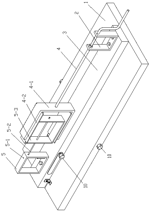
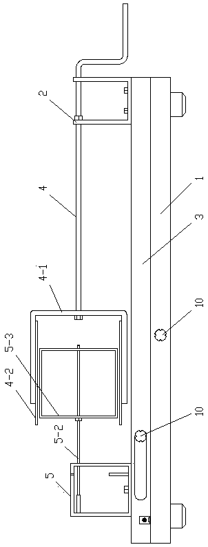
[0030] like figure 1 As shown, the present invention provides a kind of technical scheme:
[0031] A multifunctional demonstrator for electromagnetic experiments, a multifunctional demonstrator for electromagnetic experiments, comprising a base 1, a fixed plate 3, a fixed frame 5, a rotating frame 2 and a crank handle 4, the fixed plate 3 is arranged above the base 1 And it is rotationally connected with the base 1, the fixed frame 5 and the rotating frame 2 are respectively arranged on the two ends of the fixed plate 3 and fixed, the rotating frame 2 is horizontally provided with a crank handle 4, and the crank handle 4 passes through The rotating frame 2 is also rotated around the rotating frame 2, the crank 4 is connected with a U-shaped frame 4-1, and the U-shaped frame 4-1 is located between the fixed frame 5 and the rotating frame 2, and the U-shaped frame 4 -1 Bar magnets 4-2 with opposite polarities are arranged at the upper and lower ends, and a first through hole 5-...
Embodiment 2
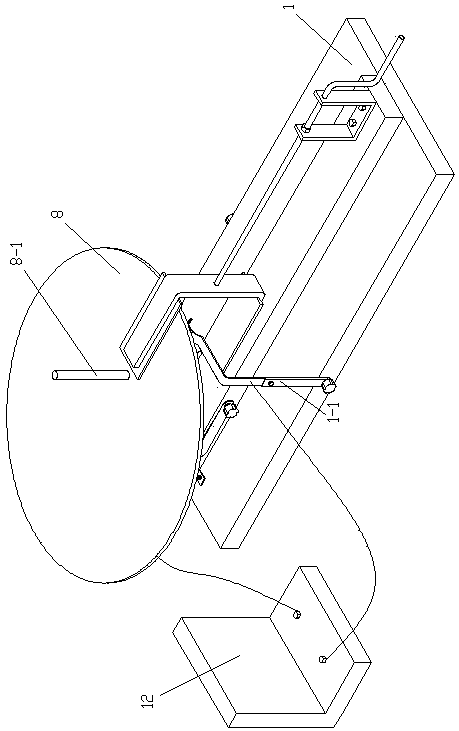
[0034] like image 3 Shown: the second technical scheme provided by the present invention:
[0035] Demonstrate the principle of Faraday generator to generate electricity.
[0036] A rotating disk is arranged in the second through hole, and the rotating shaft provided at the bottom of the rotating disk is located in the second fixed column. The height of the rotating disk is located between the upper and lower heteropolar magnets of the U-shaped frame. The bottom of the disk is in contact with the brush piece fixed on the base. Use a sensitive ammeter to connect the brush piece and the rotating shaft below the rotating disk. Shake the manual rotating shaft, and you will find that the ammeter pointer deflects obviously to one side. Change the direction of the rotating disk, and the meter pointer will The deflection direction changes, which shows that the direction of the induced current is related to the direction of the magnetic induction line cut by the rotating disk. It can...
Embodiment 3
[0038] like Figure 4 Shown: the third technical scheme provided by the present invention:
[0039] Demonstrate that a single straight conductor cuts the magnetic flux line to generate an induced current and the current-carrying straight conductor receives an Ampere force in a magnetic field.
[0040]A guide rail bracket is set under the base, and the guide rail bracket includes a bottom plate and two parallel copper tubes arranged on the bottom plate. The copper tubes are fixedly connected by a rotating piece, and the height of the copper tubes is located at the upper and lower ends of the U-shaped frame. A guide rod is placed between the magnets and two copper tubes, and the sensitive ammeter is connected to the same end of the two copper tubes, so that the guide rod slides or rolls along the left and right directions of the copper tube, and the pointer of the ammeter swings left and right. In this phenomenon, the relationship between the induced current, magnetic field, an...
PUM
 Abstract
Description
Claims
Application Information
 - R&D
- Intellectual Property
- Life Sciences
- Materials
- Tech Scout
- Unparalleled Data Quality
- Higher Quality Content
- 60% Fewer Hallucinations
Browse by: Latest US Patents, China's latest patents, Technical Efficacy Thesaurus, Application Domain, Technology Topic, Popular Technical Reports.
© 2025 PatSnap. All rights reserved.Legal|Privacy policy|Modern Slavery Act Transparency Statement|Sitemap|About US| Contact US: help@patsnap.com


