
Material conveying and discharging device of metal plates

A technology of blanking device and jacking device, which is applied in the direction of feeding device, positioning device, storage device, etc., can solve the problems of not being able to automatically feed materials and hinder waste materials from sliding out, and achieve high production efficiency, simple structure, and problems that cannot be solved automatically The effect of feeding

Inactive Publication Date: 2018-05-29
芜湖瑞鹄浩博模具有限公司
View PDF4 Cites 1 Cited by
  • Summary
  • Abstract
  • Description
  • Claims
  • Application Information

AI Technical Summary

Problems solved by technology

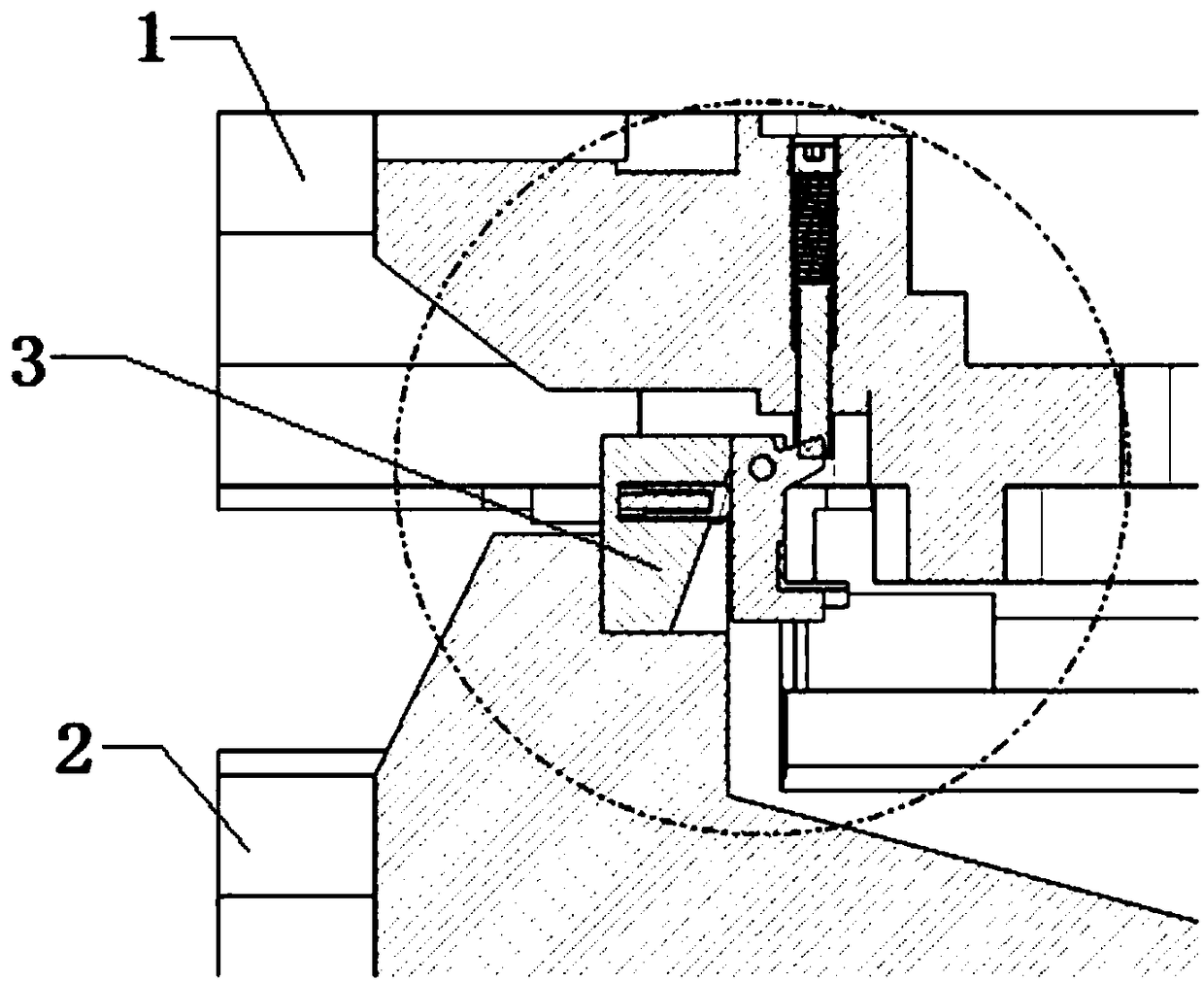
[0003] According to the deficiencies in the prior art above, the technical problem to be solved by the present invention is to propose a sheet metal feeding and blanking device, through the rotation of the rotating block and the top block to achieve the accuracy of feeding the supporting material, and through the pressing movement to drive The automatic feeding device realizes automatic feeding, which solves the problem that the traditional fixed positioner hinders the waste from sliding out and the shortcomings of not being able to automatically feed, and has the characteristics of simple structure and high production efficiency

Method used


Image

  • Material conveying and discharging device of metal plates
  • Material conveying and discharging device of metal plates
  • Material conveying and discharging device of metal plates

Examples


Embodiment Construction

[0014] Referring to the accompanying drawings, through the description of the embodiments, the specific embodiments of the present invention include the shape, structure, mutual position and connection relationship of each part, the function and working principle of each part, and the manufacturing process of the various components involved. And the method of operation and use, etc., are described in further detail to help those skilled in the art have a more complete, accurate and in-depth understanding of the inventive concepts and technical solutions of the present invention.

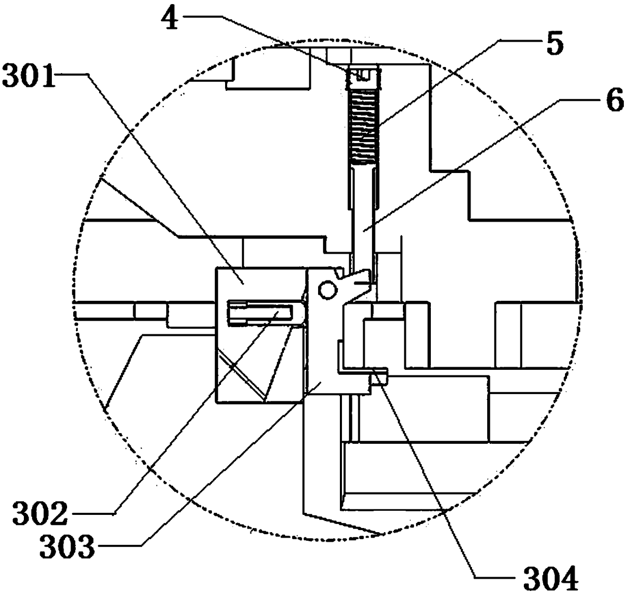
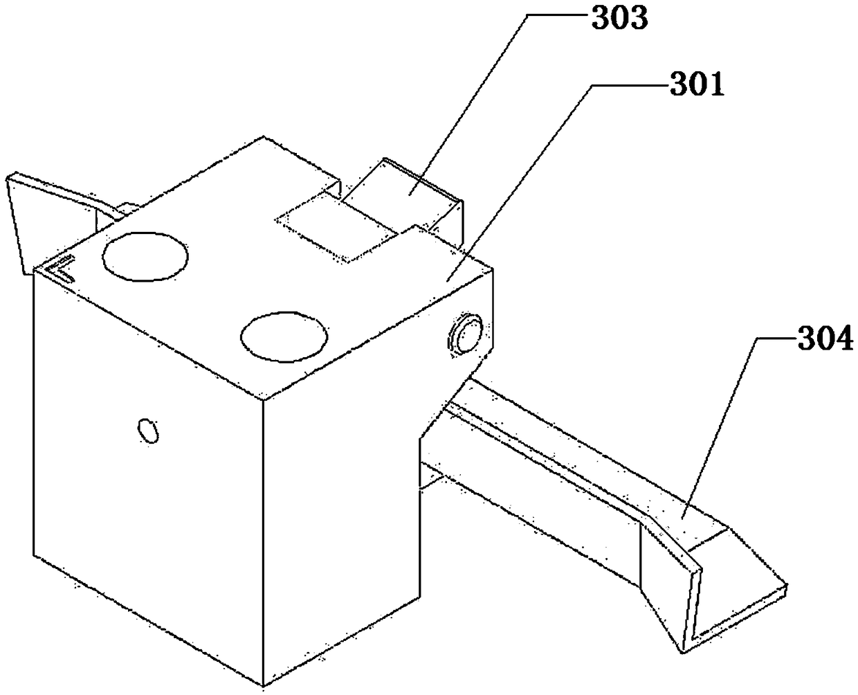
[0015] Such as Figure 1-5 As shown, the present invention proposes a sheet metal feeding and blanking mechanism including an upper mold 1, a lower mold 2, a rotary supporting device 3, a jacking device, a rotating supporting block 303 and an automatic feeding device, and the rotating supporting device The fixed seat 301 in 3 is installed on the lower mold 2, and a groove is provided on the fixed sea...


PUM


Abstract

The invention discloses a material conveying and discharging device of metal plates. The material conveying and discharging device comprises an upper mould, a lower mould a fixed base, a material ejection device, a rotary material supporting block and an automatic material conveying device; the fixed base is arranged on the lower mould; a groove is formed in the fixed base and faces to the inner side of a mould; a rotary block is rotatably arranged on the groove; the material injection device is arranged on the upper mould and clings to the top of the rotary material supporting block; a resetspring mechanism which is used for ejecting the rotary materials supporting block is arranged between the rotary material supporting block and the groove; the automatic material conveying device is arranged in the fixed base; the automatic material conveying device comprises a pressing rod and an intermittent feeding wheel; the pressing rod is vertically arranged on the upper surface of the fixedbase; and the intermittent feeding wheel is arranged on the side surface of the fixed base. By adopting the material conveying and discharging device, the problem in the prior art that a traditional fixed positioner inhibits sliding out of waste materials is solved; the defect of incapability of automatic material conveying is overcome; and the material conveying and discharging device has the characteristics of being simple in structure and high in production efficiency.

Description

technical field [0001] The invention belongs to the technical field of mold design, and in particular relates to a sheet metal feeding and blanking device. Background technique [0002] Multi-station progressive film completes many processes, including punching, bending, forming and deep drawing. The strip material cannot be blocked in any way during the feeding process. The material must be floated away from the plane of the lower die, and at the same time, the work of the punching and backflushing mechanism must not be affected. The material guide device guides the strip material along the feeding direction. Usually adopt the form of a boss, under the action of the floating top on the strip, the material is fed. The traditional material guide device installed between the mold and the sheet takes up a lot of space, resulting in a large increase in the mold body and a single function. The degree of automation is low, and the debugging is inflexible. When working, the upper ...

Claims


Application Information

Patent Timeline
IPC IPC(8): B21D37/10B21D45/04B21D43/09B21D37/12
CPCB21D37/10B21D37/12B21D43/09B21D45/04
Inventor 何虎余亮李小昌严应红
Owner 芜湖瑞鹄浩博模具有限公司
Learn More