Automatic cover safety valve equipment and safety valve for battery production

A technology for safety valves and batteries, which is applied in the construction of lead-acid batteries, lead-acid batteries, battery pack components, etc. It can solve problems that affect product quality stability, low efficiency, and different depths of safety valve covers, and solve the problems that cannot be automatically Normal feeding problem, easy to use, avoid sticking effect

Pending Publication Date: 2019-01-04
ZHEJIANG TIANNENG BATTERY JIANGSU
View PDF0 Cites 0 Cited by
  • Summary
  • Abstract
  • Description
  • Claims
  • Application Information

AI Technical Summary

Problems solved by technology

[0002] At present, the safety valves of valve-regulated lead-acid batteries in the industry are generally installed manually one by one. The higher the temperature, the replacement of labor by automation has become a tr

Method used


Image

  • Automatic cover safety valve equipment and safety valve for battery production
  • Automatic cover safety valve equipment and safety valve for battery production
  • Automatic cover safety valve equipment and safety valve for battery production

Examples


Example Embodiment

[0032] Implementation mode 1:

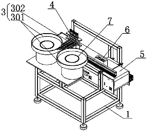
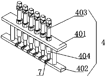
[0033] This embodiment provides an automatic cover safety valve device for battery production, such as Figure 1 to 5 As shown, it is mainly composed of a frame 1 and a safety valve feeding device 3 arranged on the frame 1, a safety valve pressing device 4 and a battery conveying device 5. The safety valve feeding device 3 consists of two vibrating discs 301 and six conveying devices Each vibrating disk 301 is connected with the entrance of three conveying rails 302, and the exits of the six conveying rails 302 are connected with the safety valve according to the cover device 4. The vibrating disk 301 in this embodiment is specially made, and the vibrating disk 301 The treatment process includes disc surface twill, channel embossing, and Teflon spraying to ensure continuous and stable feeding of the safety valve 7; the safety valve cover device 4 is composed of a base plate 401, a safety valve positioning mold 402, six cover cylinders 403, and It ...

Example Embodiment

[0037] Implementation mode 2:

[0038] This embodiment is a further improvement of Embodiment 1. The main improvement lies in the following: In Embodiment 1, because the safety valve is fixed according to the position of the cover device 4, that is, the position of the safety valve positioning mold 402 is fixed, the equipment can only be applied to The battery 6 with the cover to be pressed in one size has a narrow application range and cannot be calibrated by adjusting the position of the safety valve positioning mold 402 if positioning deviation occurs. However, this embodiment can effectively solve the above-mentioned defects.

[0039] Specifically, in this embodiment, as Figure 8 with 9 The safety valve pressing device 4 also has an adjusting plate 407 and two adjusting rods 408. One side of the adjusting plate 407 is fixed on the frame 1, and the other has two waist-shaped through holes 409. The safety valve pressing device 4 The base plate 401 is fixed to the adjusting plate...

Example Embodiment

[0041] Implementation mode 3:

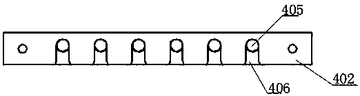
[0042] This embodiment is a further improvement of the second embodiment. The main improvement lies in: in the second embodiment, the battery 6 to be pressed is smoothly transported under the safety valve positioning mold 402 only by the battery transport device 5. After the safety valve positioning through holes 406 on the positioning mold 402 are aligned with the acid injection holes on the battery 6 to be pressed, the automatic pressing of the safety valve 7 can be realized more effectively. Therefore, only the battery conveying device 5 At that time, when the battery 6 to be pressed is located under the safety valve positioning mold 402, the battery conveying device 5 needs to be suspended. After the safety valve pressing device 4 presses the safety valve 7 onto the acid injection holes of the battery 6 to be pressed , Can start the conveying mechanism again to convey the installed battery to the next process, and at the same time move the next...


PUM

PropertyMeasurementUnit
Widthaaaaaaaaaa

Abstract

The invention relates to the technical field of lead-acid battery, which discloses an automatic cover safety valve device and a safety valve used for battery production. The battery conveying device is located below the safety valve pressing cover device and is used for conveying the battery to be pressed on the safety valve pressing cover device directly below the safety valve pressing cover device. The discharge port of the relief valve feeding device is engaged with one side of the relief valve pressing cover device for feeding the relief valve positioned thereon to the lower part of the relief valve pressing cover device and to the upper part of the battery to be pressed cover. The device realizes the valve-regulated lead-acid battery full-automatic cover safety valve, replaces the original manual cover safety valve process, reduces the labor cost, increases the production efficiency by 400%, and helps to improve the product quality stability; The structure of the safety valve solves the sticking phenomenon of the surface of the safety valve and the vibration disk and the sticking phenomenon of the bottom edge and the closed top surface between the adjacent safety valves, thereby ensuring that the vibration disk can continuously feed the safety valve automatically, and further realizing the automatic cover valve through the automatic equipment.

Description

technical field [0001] The invention relates to the technical field of lead-acid batteries, in particular to the development and application of a device for fully automatic safety valve placement in the production of valve-regulated lead-acid batteries and the safety valve. Background technique [0002] At present, the safety valves of valve-regulated lead-acid batteries in the industry are generally installed manually one by one. The higher the temperature, the replacement of labor by automation has become a trend, and it is of great significance to reduce labor costs for enterprises; therefore, it is imminent to invent a device that can automatically place safety valves in the production of valve-regulated lead-acid batteries. Contents of the invention [0003] Purpose of the invention: Aiming at the problems existing in the prior art, the present invention provides an automatic cover safety valve device and safety valve for battery production. The manual cover safety v...

Claims


Application Information

Patent Timeline
IPC IPC(8): H01M2/12H01M10/12H01M50/30
CPCH01M10/12H01M50/394Y02E60/10Y02P70/50
Inventor 朱成龙陈金国伍锦华丁建中钱炜史良洋
Owner ZHEJIANG TIANNENG BATTERY JIANGSU
Why Eureka
Try Eureka