Tank body support unit welding fixture and air tank production line

A welding fixture and bracket group technology, applied in the field of machinery, can solve the problems of inconsistent positions, uneven welding quality, and inability to guarantee the welding accuracy of brackets, and achieves the requirements of reducing requirements, improving production efficiency, and improving production efficiency and production quality. Effect

Pending Publication Date: 2018-05-29
浙江精匠智能科技有限公司
View PDF11 Cites 4 Cited by
  • Summary
  • Abstract
  • Description
  • Claims
  • Application Information

AI Technical Summary

Problems solved by technology

However, in this way of operation, not only the accuracy of the welding of the bracket cannot be guaranteed, but also the position of each welded on the tank body is inconsistent, and the quality of the welding is also affected by the quality of manpower.

Method used


Image

  • Tank body support unit welding fixture and air tank production line
  • Tank body support unit welding fixture and air tank production line
  • Tank body support unit welding fixture and air tank production line

Examples


Embodiment 1

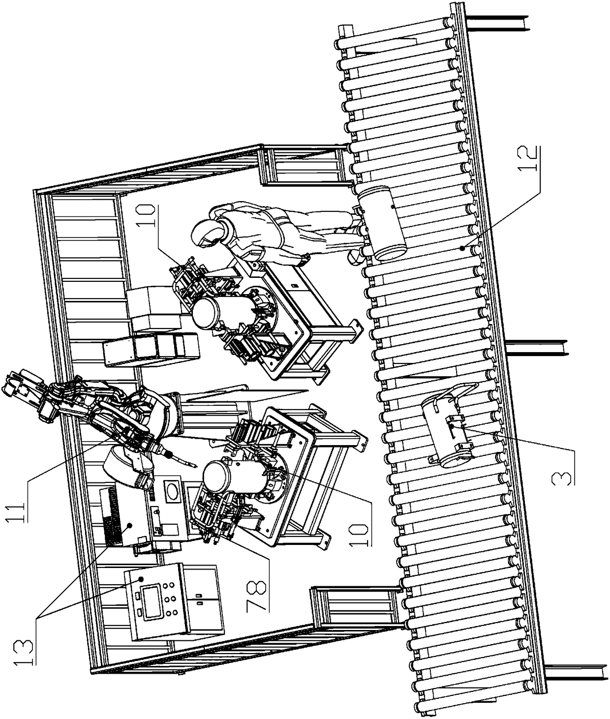
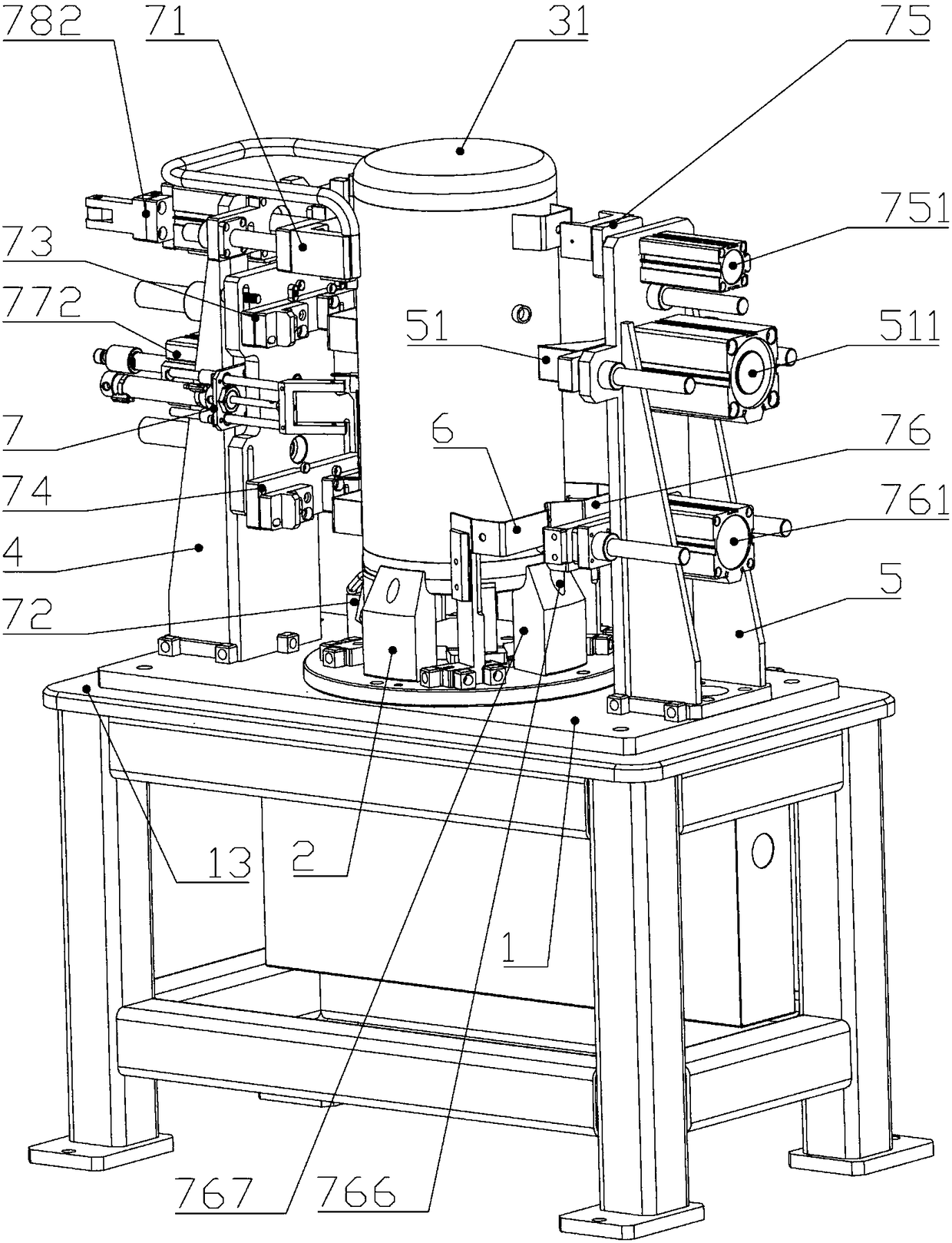
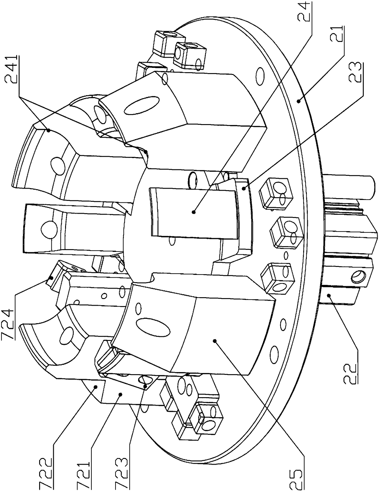
[0046] Embodiment one: if Figure 1-6 As shown, a welding jig for a tank bracket group includes a base 1, the base 1 is provided with a tank lower positioning mechanism 2, and the tank lower positioning mechanism 2 is vertically provided with a tank mounting position 31; the tank The peripheral side of the lower body positioning mechanism 2 is provided with a compression frame 4 and a positioning frame 5, and the compression frame 4 and the positioning frame 5 are telescopically provided with a bracket group positioning feeding mechanism 7, and a welding raw material is positioned on the bracket group positioning feeding mechanism 7. The bracket group 6, the bracket group positioning feeding mechanism 7 drives the bracket group 6 to the welding position on the outer end surface of the tank installation position 3, and the positioning frame 5 is also provided with a tank body side positioning mechanism 51.

[0047]This technical solution specifically describes a welding fixture...


PUM


Abstract

The invention discloses a tank body support unit welding fixture and an air tank production line and belongs to the technical field of machinery. The tank body support unit welding fixture comprises abase, a tank body bottom positioning mechanism is arranged on the base, and a tank mounting site is vertically arranged on the tank body bottom positioning mechanism; a compressing rack and a positioning rack are arranged around the tank body bottom positioning mechanism; a support unit positioning and feeding mechanism is arranged on the compressing rack and the positioning rack in telescopic manner; a welding material support unit is positioned on the support unit positioning and feeding mechanism; the support unit positioning and feeding mechanism drives the welding material support unit to a welding site on the outer end face of the tank body mounting site; a tank body side positioning mechanism is also arranged on the positioning rack. All supports around an air tank can be welded bysingle clamping through a welding robot with no need for manpower; each support corresponds to one feeding mechanism; it can be ensured that the results of all welding procedures remain uniform; production efficiency and production quality are greatly higher than those of the prior art.

Description

technical field [0001] The invention belongs to the technical field of machinery, in particular to a welding jig for a tank bracket group and a gas storage tank production line. Background technique [0002] At present, air compressor is a kind of equipment used to compress gas, which is widely used in all walks of life. Air storage tank is an essential part of an air compressor, and the market demand for this product is also increasing. But the production process of the gas storage tank is still very backward at present, especially those brackets on the outer periphery of the gas storage tank, there are many, and the shape of each bracket is different, and the installation position is also different. In the prior art, all the brackets are manually welded one by one. However, in this way of operation, not only the accuracy of the welding of the brackets cannot be guaranteed, but also the position of each welded on the tank body is inconsistent, and the quality of the weldi...

Claims


Application Information

Patent Timeline
Patent Type & Authority Applications(China)
IPC IPC(8): B23K37/04B23K37/00
CPCB23K37/00B23K37/0443
Inventor 余丁超
Owner 浙江精匠智能科技有限公司
Why Eureka
Try Eureka