An Aircraft Hydraulic Braking System with Automatic Braking Capability

A technology of automatic braking and braking system, applied in the direction of aircraft braking arrangements, automatic starting devices, brakes, etc., can solve problems such as difficulty in troubleshooting and positioning, low reliability in use, and complicated design and configuration, so as to improve runway utilization and Equipment utilization rate, high reliability, reasonable and feasible structure

Active Publication Date: 2020-05-19
XIAN AVIATION BRAKE TECH
View PDF23 Cites 0 Cited by
  • Summary
  • Abstract
  • Description
  • Claims
  • Application Information

AI Technical Summary

Problems solved by technology

[0005] The purpose of the present invention is to overcome the problems existing in the prior art, such as complex design and configuration, frequent faults, difficulty in troubleshooting and positioning, low reliability in use, and various logical relationships that even cause potential safety hazards. The present invention proposes a Aircraft hydraulic brake system with automatic braking capability,

Method used


Image

  • An Aircraft Hydraulic Braking System with Automatic Braking Capability
  • An Aircraft Hydraulic Braking System with Automatic Braking Capability
  • An Aircraft Hydraulic Braking System with Automatic Braking Capability

Examples


Embodiment 1

[0026] The front landing gear wheels of modern aircraft generally do not have brakes, and brake devices are equipped on the wheels of the two main landing gears. The two aircraft main landing gears are usually arranged symmetrically on both sides of the aircraft fuselage. In this embodiment, one of the main landing gear and one wheel is installed as an example to illustrate the aircraft hydraulic braking system with automatic braking capability of the present invention. The emergency braking system adopts the prior art.

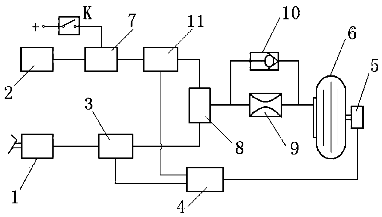
[0027] In this embodiment, the automatic braking is set to one level, that is, only one level. The automatic brake anti-skid valve adopts an independent anti-skid valve, and an electro-hydraulic servo valve is used as the anti-skid valve.

[0028] An aircraft hydraulic braking system with automatic braking capability includes a hydraulic brake valve 1, an electro-hydraulic servo valve 3, a second electro-hydraulic servo valve 11, a pressure reducing valve 2...

Embodiment 2

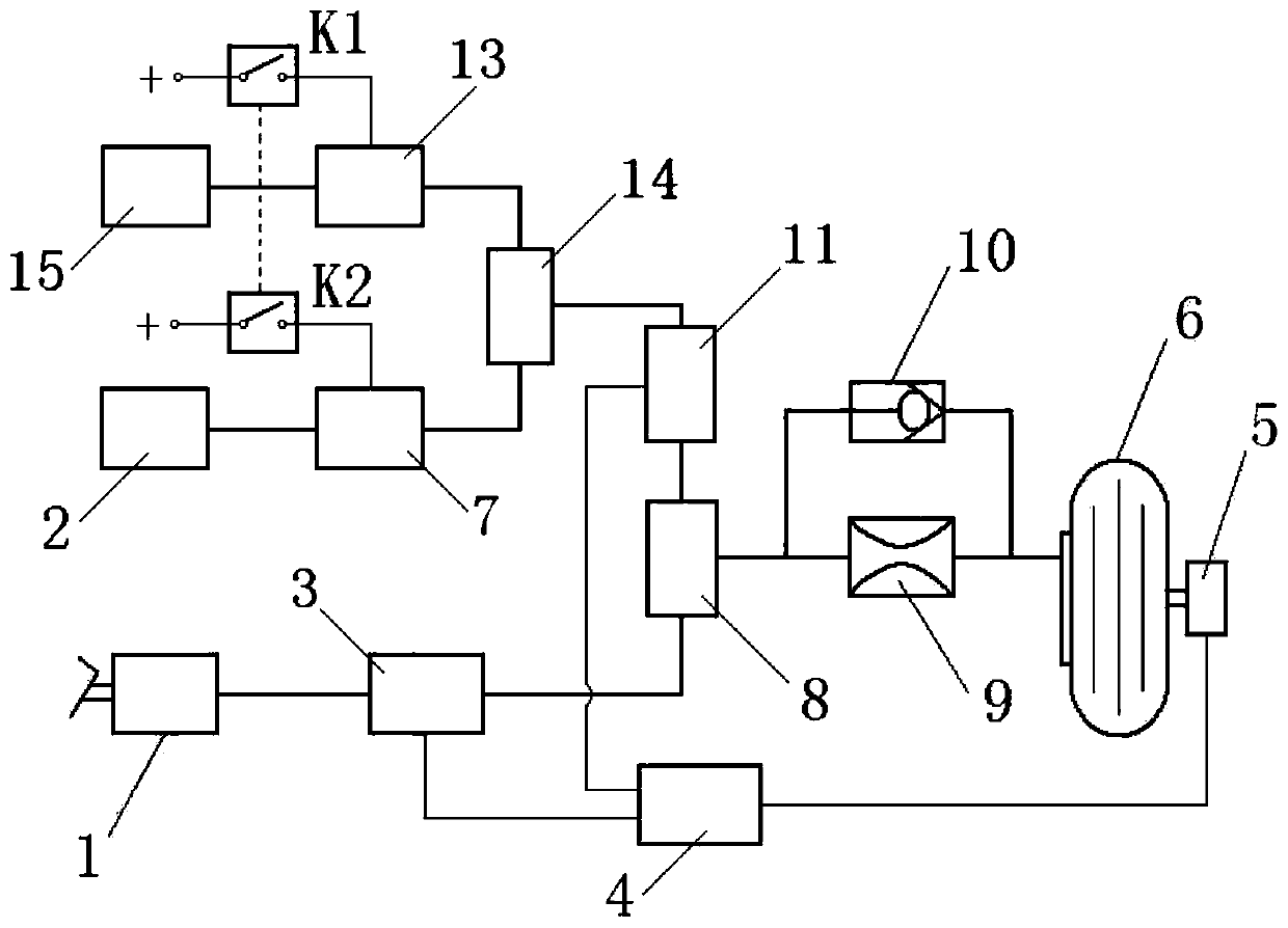
[0046] This embodiment is an aircraft hydraulic braking system with automatic braking capability. The difference from Embodiment 1 is that this embodiment is a two-stage automatic braking; the decompression pressure of one decompression valve is lower than that of the other decompression valve. Reduced pressure. The automatic brake anti-skid valve adopts an independent anti-skid valve, and an electro-hydraulic servo valve is used as the anti-skid valve.

[0047] This embodiment includes: hydraulic brake valve 1, electro-hydraulic servo valve 3, second electro-hydraulic servo valve 11, pressure reducing valve 2, second pressure reducing valve 15, hydraulic valve 7, second hydraulic valve 13, switching valve 8. The second conversion valve 14, the first automatic brake switch K1, the second automatic brake switch K2, the throttle 9, the one-way valve 10, the speed sensor 5 and the anti-skid control box 4.

[0048] Among them, the hydraulic brake valve 1, the electro-hydraulic se...


PUM


Abstract

Disclosed is an airplane hydraulic braking system with the automatic braking capacity. A first-stage automatic braking system is composed of a hydraulic braking valve, electro-hydraulic servo valves,a speed sensor, an antiskid control box, an automatic braking switch K and a conversion valve. A second-stage automatic braking system is composed of a hydraulic braking valve, two electro-hydraulic servo valves, a speed sensor, an antiskid control box, two automatic braking switches, two conversion valves, two hydro-electric valves, two conversion valves, two pressure reducing valves, a throttleand a one-way valve. The automatic braking capacity is achieved, the operation selecting range of a normal braking system is completed and expanded, and braking mode selection of automatic braking isprovided for a driver; the potential of the braking system is given to full play advantageously, and the landing sliding distance is shortened by 35%; and the airplane hydraulic braking system has thecharacteristics of reasonable and feasible structure, flexible, convenient and rapid using, high reliability and the like, and the problems of implying of safety accident hidden dangers, difficult trouble shooting and the like are avoided.

Description

technical field [0001] The invention relates to an aircraft wheel hydraulic braking system, in particular to an aircraft hydraulic braking system with automatic braking capability. Background technique [0002] The aircraft wheel brake system is a component of modern aircraft landing gear, and is the basic guarantee equipment for the safe operation of aircraft take-off, landing roll and ground taxi control. Prevent punctured tires. Ground traffic congestion is a growing problem in many cities that are now rapidly modernizing. Air traffic is no exception, with flights arriving and departing from airports lining up on the runway. With the development of civil aviation, the provision of airport runway resources and the utilization of airport runway resources have a significant impact on safe and fast inbound and outbound flights. How to shorten the runway distance as soon as possible to make the aircraft exit the runway is an important issue in aviation engineering technology...

Claims


Application Information

Patent Timeline
Patent Type & Authority Patents(China)
IPC IPC(8): B60T7/12B60T13/66B60T13/68B64C25/44
CPCB60T7/12B60T13/662B60T13/686B64C25/44
Inventor 何永乐何文静丛晨
Owner XIAN AVIATION BRAKE TECH
Why Eureka
Try Eureka