Aircraft hydraulic brake system with independent anti-skid function

A technology for aircraft hydraulic and braking systems, applied in aircraft braking arrangements, vehicle components, brakes, etc., can solve problems such as difficult troubleshooting, low reliability, and complex design and configuration, and improve runway utilization and equipment Utilization rate, high reliability, reasonable structure and feasible effect

Active Publication Date: 2021-02-26
XIAN AVIATION BRAKE TECH
View PDF17 Cites 0 Cited by
  • Summary
  • Abstract
  • Description
  • Claims
  • Application Information

AI Technical Summary

Problems solved by technology

[0005] In order to overcome the problems existing in the prior art, such as complex design and configuration, frequent failures, difficulty in troubleshooting and positioning, low reliability in use, multiple logical relationships and even potential safety hazards, the present invention proposes an aircraft with an independent anti-skid function hydraulic brake system

Method used


Image

  • Aircraft hydraulic brake system with independent anti-skid function
  • Aircraft hydraulic brake system with independent anti-skid function

Examples


Embodiment 1

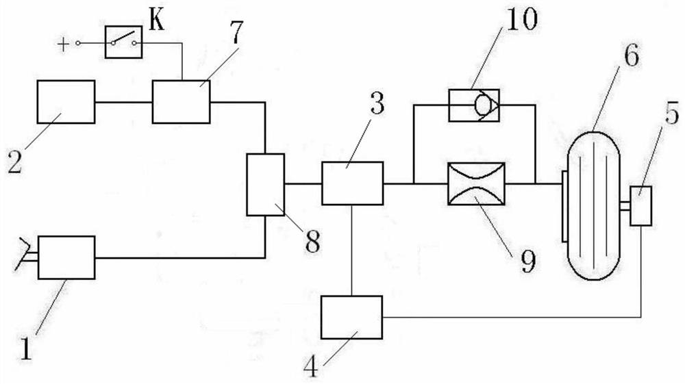
[0023] In this embodiment, the automatic braking is set to one level. The automatic brake anti-skid valve adopts an electro-hydraulic servo valve 3 as a common anti-skid valve.

[0024] An aircraft hydraulic braking system with automatic braking capability, the system comprises: hydraulic braking valve 1, electro-hydraulic servo valve 3, pressure reducing valve 2, hydraulic-electric valve 7, first switching valve 8, automatic braking switch K, throttle 9, one-way valve 10, speed sensor 5 and anti-skid control box 4.

[0025] Among them, hydraulic brake valve 1, electro-hydraulic servo valve 3, speed sensor 5 and anti-skid control box 4 constitute a normal braking system. The normal braking system is set according to the prior art.

[0026] Automatic brake switch K, pressure reducing valve 2, hydraulic valve 7, first switching valve 8, throttle 9, one-way valve 10, speed sensor 5, and anti-skid control box 4 form an automatic braking system. The speed sensor 5, the anti-skid...

Embodiment 2

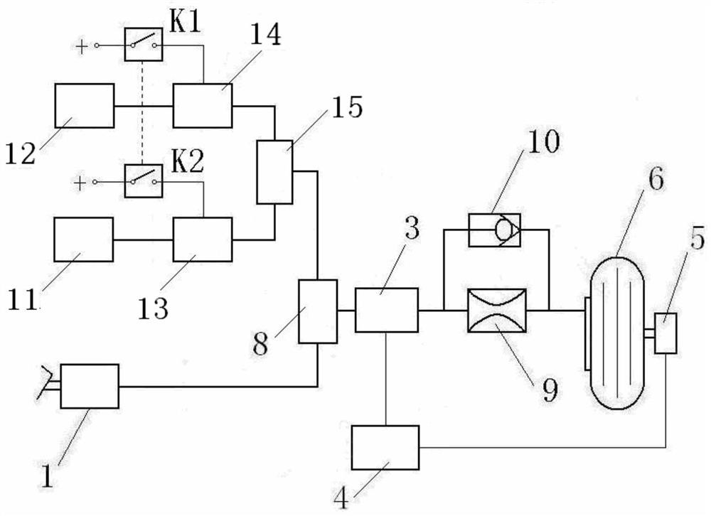
[0036] The difference between this embodiment and Embodiment 1 is that the automatic braking system is two-level. Two-stage automatic braking is set, and the pressure reduction pressure of one pressure reducing valve is lower than that of the other pressure reducing valve.

[0037] This embodiment is an aircraft hydraulic braking system with automatic braking capability, including a hydraulic braking valve 1, an electro-hydraulic servo valve 3, a first pressure reducing valve 11, a second pressure reducing valve 12, a first hydraulic-electric valve 13, a first pressure reducing valve 13, Two hydraulic valve 14 , first switching valve 8 , second switching valve 15 , first automatic brake switch K1 , second automatic brake switch K2 , throttle 9 , one-way valve 10 , speed sensor 5 and anti-skid control box 4 .

[0038] Among them, hydraulic brake valve 1, electro-hydraulic servo valve 3, speed sensor 5 and anti-skid control box 4 constitute a normal braking system. The first a...


PUM


Abstract

An aircraft hydraulic braking system with an independent anti-skid function, which consists of an automatic brake switch K, a pressure reducing valve, a hydraulic valve, a first switching valve, a throttle, a one-way valve, a speed sensor and an anti-skid control box. Automatic brake system: composed of the first automatic brake switch K1, the second automatic brake switch K2, the first pressure reducing valve, the second pressure reducing valve, the first hydraulic valve, the second hydraulic valve, the electrohydraulic servo valve, the first The switching valve, the second switching valve, the throttle, the one-way valve, the speed sensor and the anti-skid control box form the automatic braking system of the secondary braking. The invention uses independent or shared anti-skid valves to perform anti-skid control, so that the normal braking system of the aircraft has automatic braking capability, improves and expands the operating range of the normal braking system, provides the driver with the choice of automatic braking methods, and shortens the landing roll distance by 35%. , which ensures the safety of aircraft takeoff and landing, improves the utilization rate of airport runways and equipment utilization, and has obvious economic, social and military benefits.

Description

technical field [0001] The invention relates to an aircraft wheel hydraulic braking system, in particular to an aircraft hydraulic braking system with automatic braking capability. Background technique [0002] Aircraft wheel braking system is an integral part of modern aircraft landing gear. It is the basic guarantee equipment for the safe operation of aircraft take-off, landing roll and ground taxi operation. Prevent tire blowout. Ground traffic congestion is a growing problem in many cities now accelerating modernization. Air traffic is no exception, with airport arrivals and departures lined up on the runway. With the development of civil aviation, the provision of airport runway resources and the utilization of airport runway resources have a very prominent impact on safe and fast entry and exit flights. Major issues that need to be studied by personnel and related parties. If the aircraft can be braked and stopped within the shortest possible rolling distance, the ...

Claims


Application Information

Patent Timeline
Patent Type & Authority Patents(China)
IPC IPC(8): B64C25/46B60T8/17B60T13/68
CPCB60T8/1703B60T13/686B64C25/46
Inventor 何永乐何文静李萍
Owner XIAN AVIATION BRAKE TECH
Why Eureka
Try Eureka