exhaust pipe for vehicle

A technology for exhaust pipes and vehicles, which is applied in the direction of exhaust devices, machines/engines, mechanical equipment, etc. It can solve the problems of poor noise reduction effect at the wire mesh, and achieve the effect of sound reduction and noise reduction

Active Publication Date: 2019-07-26
张翼
View PDF1 Cites 0 Cited by
  • Summary
  • Abstract
  • Description
  • Claims
  • Application Information

AI Technical Summary

Problems solved by technology

[0004] The purpose of the present invention is to provide an exhaust pipe for vehicles, which solves the problem of poor sound attenuation effect at the wire mesh in the prior art

Method used


Image

  • exhaust pipe for vehicle
  • exhaust pipe for vehicle
  • exhaust pipe for vehicle

Examples


Embodiment Construction

[0031] The embodiments of the present invention will be described in detail below with reference to the accompanying drawings, but the present invention can be implemented in many different ways defined and covered by the claims.

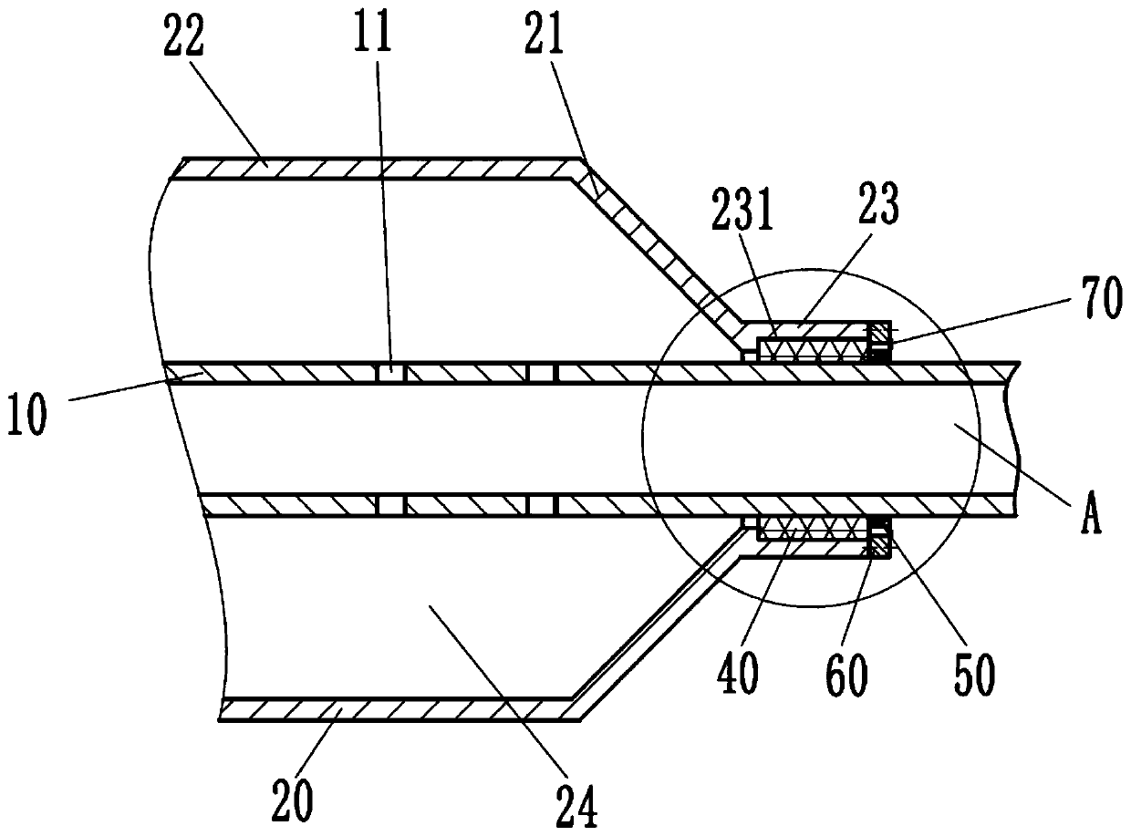
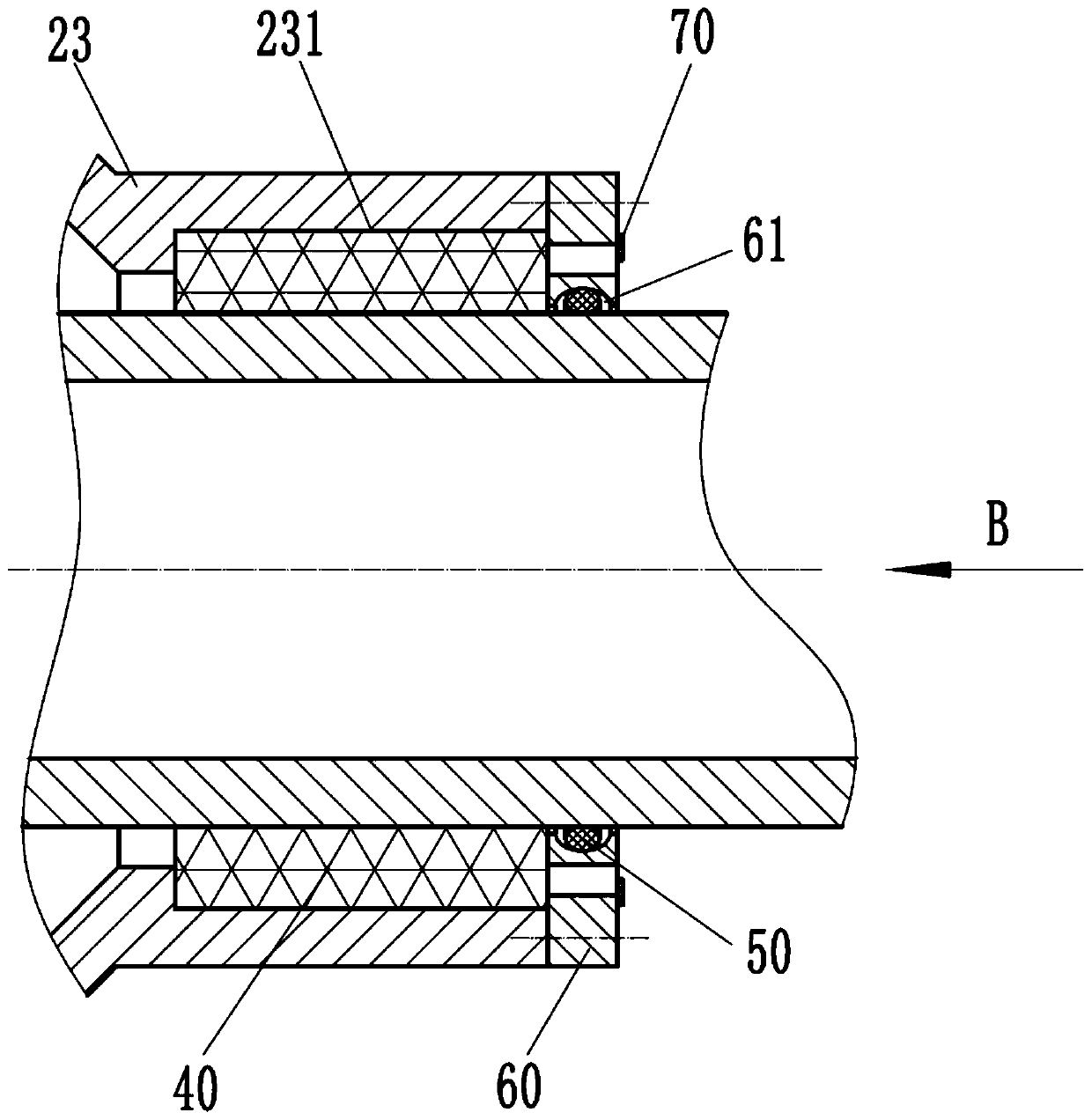
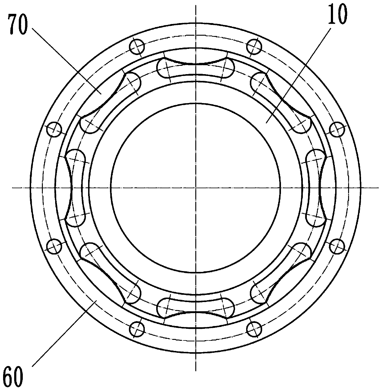
[0032] Refer below Figure 1 to Figure 7 To further explain this application, such as figure 1 , figure 2 , image 3 and Figure 4 The shown exhaust pipe for vehicles includes: a second pipe part 20, an inner pipe 10 arranged in the second pipe part 20, an inner wall arranged at the end of the second pipe part 20 and the The wire mesh 40 between the inner tubes 10, the baffle 60 and the ring-shaped baffle 70, the baffle 60 is sleeved on the inner tube 10 and installed on the end face of the end of the second tube part 20 Specifically, the baffle 60 is installed on the end face of the end of the second pipe part 20 through the screws provided in the screw through hole 62 on the baffle 60, and the left end face of the baffle 60 is close to the W...


PUM


Abstract

The invention provides an exhaust pipe for a vehicle. The exhaust pipe comprises a second pipe part, an inner pipe, a metal wire net, a baffle and a ring-shaped blocking piece, the inner pipe is arranged in the second pipe part, and the metal wire net is arranged between the inner wall of the tail end of the second pipe part and the inner pipe; and the baffle is arranged on the inner pipe in a sleeving mode and mounted on the end face of the tail end of the second pipe part, the left end face of the baffle is tightly attached to the metal wire net, the baffle is provided with a plurality of strip-shaped through holes, and the ring-shaped blocking piece is welded to the right end face of the baffle and shields the local parts of openings of the right ends of the strip-shaped through holes.According to the exhaust pipe for the vehicle, and due to the fact the structure is adopted, the silencing effect of the exhaust pipe is excellent.

Description

technical field [0001] The invention relates to an exhaust pipe, in particular to an exhaust pipe for vehicles. Background technique [0002] The exhaust pipe is a part of the engine exhaust system. The exhaust system mainly includes the exhaust manifold, the exhaust pipe and the muffler. Generally, the three-stage catalytic converter that controls the emission of engine pollutants is also installed in the exhaust system. The exhaust The pipe generally includes a front exhaust pipe and a rear exhaust pipe. [0003] Chinese patent CN201120166100.3 discloses an exhaust pipe comprising an outer pipe, an inner pipe having a plurality of through holes and a catalytic converter. The outer tube includes a first tube part and a second tube part. Wherein, a step portion is provided between the first pipe portion and the second pipe portion for preventing condensed water from flowing to the catalytic converter along the inner wall of the second pipe portion. Due to the restriction ...

Claims


Application Information

Patent Timeline
Patent Type & Authority Patents(China)
IPC IPC(8): F01N13/08F01N1/08
CPCF01N1/08F01N13/08
Inventor 陈孜然
Owner 张翼
Why Eureka
Try Eureka