LED (light emitting diode) display screen case front-back double-hole assembling structure

A LED display and cabinet technology, applied in the direction of instruments, identification devices, etc., can solve the problems of small space for LED display installation, LED display cannot be spliced, and affect the visual effect of the display, so as to achieve flexible assembly methods, Effect of preventing deformation or displacement and small gaps

Pending Publication Date: 2018-05-29
FUJIAN QIANGLI PHOTOELECTRICITY
View PDF0 Cites 3 Cited by
  • Summary
  • Abstract
  • Description
  • Claims
  • Application Information

AI Technical Summary

Problems solved by technology

[0002] At present, most of the splicing between the LED display cabinets is in the form of buckle, that is, the two cabinets are assembled and fixed through the letter buckle that cooperates with each other. Although this assembly method has the advantage of easy installation, the letter buckle The structure is complex and there are many parts. As we all know, the accuracy of the mechanical structure will decrease with the increase of parts, which will also lead to larger seams between adjacent boxes after splicing LED boxes; but now In the field of LED display screens, especially for high-density display screens, the joints between the cabinets directly affect the visual effect of the display screen; It is installed, but the space where the LED display is installed is small, especially between the back of the LED display and the installed wall or other load-carrying objects, or cannot meet the activity requirements of the buckle, which will lead to the failure of the LED display. stitching

Method used


Image

  • LED (light emitting diode) display screen case front-back double-hole assembling structure
  • LED (light emitting diode) display screen case front-back double-hole assembling structure
  • LED (light emitting diode) display screen case front-back double-hole assembling structure

Examples


Embodiment Construction

[0035] In order to make the technical problems, technical solutions and beneficial effects to be solved by the present invention clearer and clearer, the present invention will be further described in detail below in conjunction with the accompanying drawings and embodiments. It should be understood that the specific embodiments described here are only used to explain the present invention, not to limit the present invention.

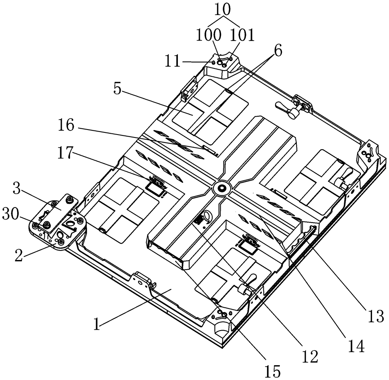
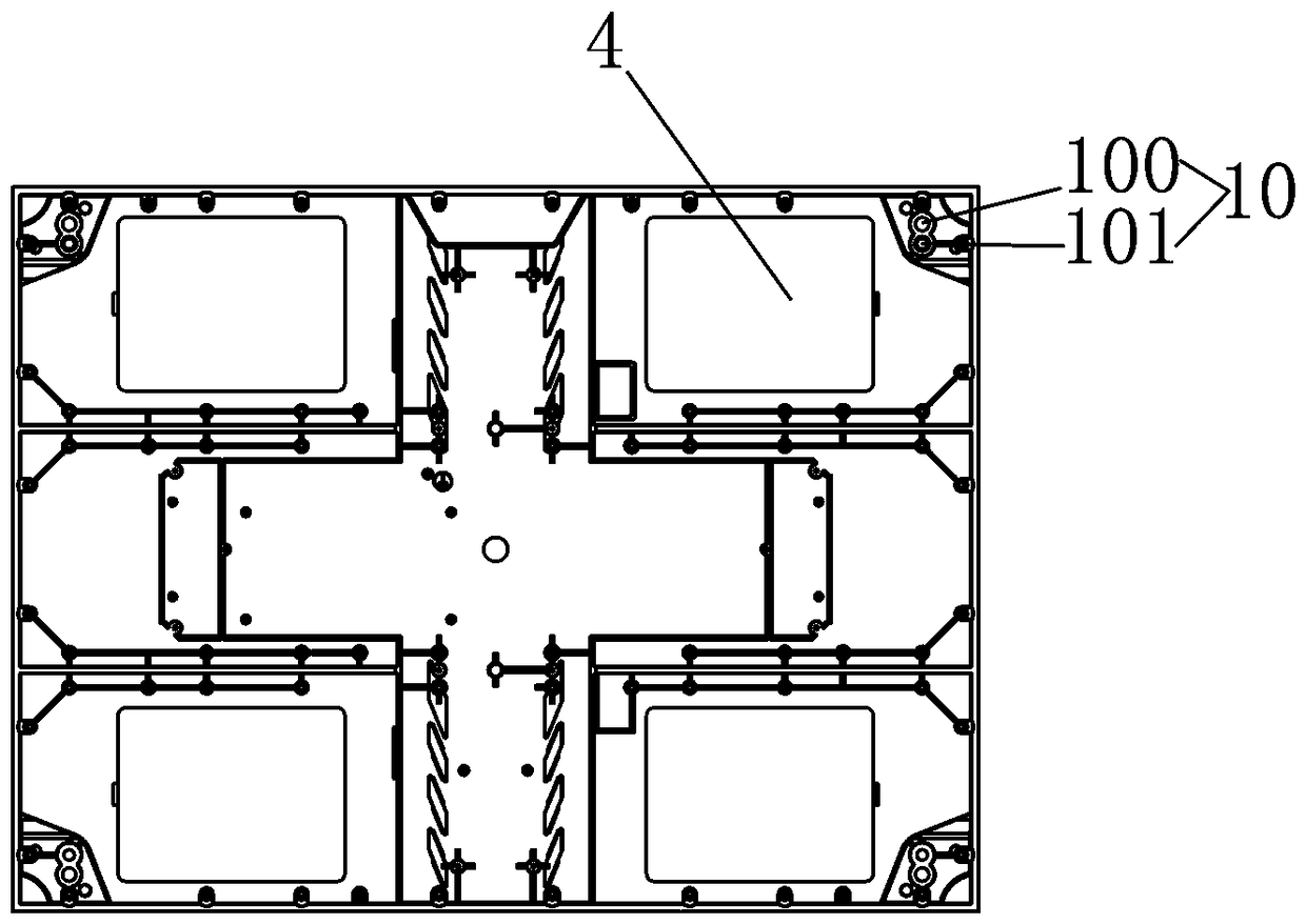
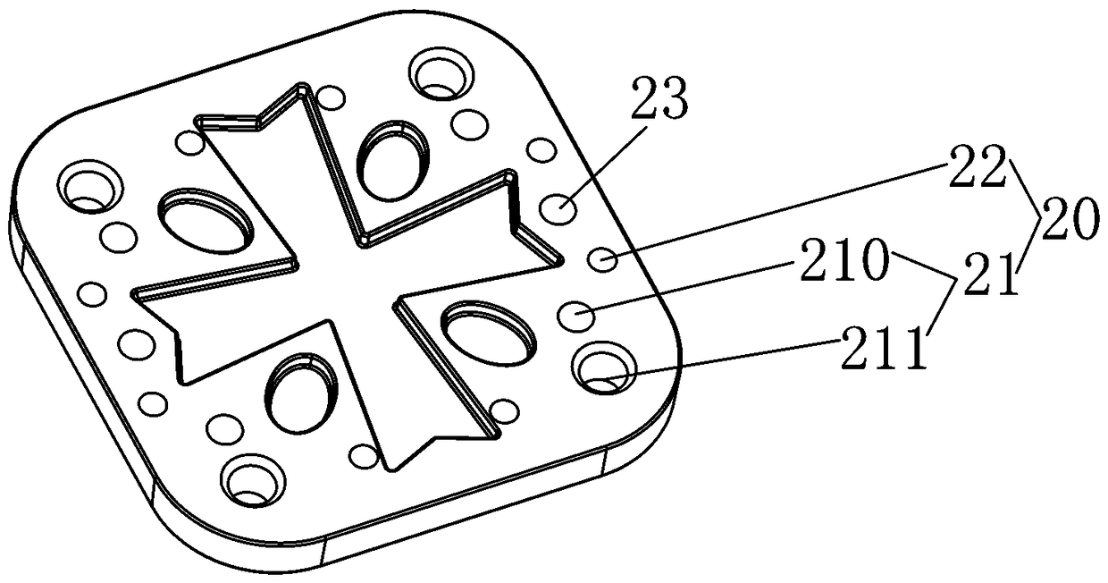
[0036] refer to Figure 1 to Figure 5 , a double-hole splicing structure at the front and back of the LED display box, including a backboard 1 and a splicing piece 2 located on the back of the backboard 1, and four corners of the backboard 1 are provided with splicing holes 10 penetrating through the backboard 1 The splicing piece 2 is divided into four positioning units 20 by mutually perpendicular X symmetry axes and Y symmetry axes, and two adjacent positioning units 20 are distributed symmetrically along the X symmetry axis or the Y symmetry axis, e...


PUM


Abstract

The invention provides an LED display screen case front-back double-hole assembling structure. The LED display screen case front-back double-hole assembling structure is composed of an assembling piece and assembling holes matched with the assembling piece. The LED display screen case front-back double-hole assembling structure can be assembled in front of or at the back of an LED display screen case and is in an assembling structure with tiny assembling seams. The LED display screen case front-back double-hole assembling structure comprises a back plate and the assembling piece arranged on the back surface of the back plate, the four corners of the back plate are provided with the assembling holes penetrating through the back plate; the assembling piece is uniformly divided into four positioning units through an X axis of symmetry and a Y axis of symmetry, every two neighboring positioning units are symmetrically distributed along the X axis of symmetry or the Y axis of symmetry, andevery positioning unit is provided with a mounting hole matched with the corresponding assembling hole; the assembling holes are matched with the mounting holes to connect the corners of the back plate to the positioning units.

Description

technical field [0001] The invention relates to the field of LED display screens, in particular to a double-hole splicing structure at the front and rear of an LED display screen box. Background technique [0002] At present, most of the splicing between the LED display cabinets is in the form of buckle, that is, the two cabinets are assembled and fixed through the letter buckle that cooperates with each other. Although this assembly method has the advantage of easy installation, the letter buckle The structure is complex and there are many parts. As we all know, the accuracy of the mechanical structure will decrease with the increase of parts, which will also lead to larger seams between adjacent boxes after splicing LED boxes; but now In the field of LED display screens, especially for high-density display screens, the joints between the cabinets directly affect the visual effect of the display screen; It is installed, but the space where the LED display is installed is s...

Claims


Application Information

Patent Timeline
IPC IPC(8): G09F9/33
CPCG09F9/33
Inventor 洪荣辉程路祥
Owner FUJIAN QIANGLI PHOTOELECTRICITY
Why Eureka
Try Eureka