Telescopic lever hoisting equipment

A technology of lifting equipment and levers, which is applied in the field of retractable lever lifting equipment, can solve the problems of high labor intensity, complex mechanism, harsh environment, etc., and achieve the effect of reducing lifting mechanism, ensuring stability, and simple overall structure

Active Publication Date: 2018-06-01
TAIYUAN UNIVERSITY OF SCIENCE AND TECHNOLOGY
View PDF9 Cites 5 Cited by
  • Summary
  • Abstract
  • Description
  • Claims
  • Application Information

AI Technical Summary

Problems solved by technology

[0003] Existing lifting equipment usually has a huge structure and complex mechanism. For some very special workplaces, the environment is harsh and the working space is limited. Working in this environment, it is impossible to use large lifting equipment to carry or move goods, and only rely on workers To carry or move, the traditional way of carrying is that the workers carry it by hand and use small lifting equipment such as chain hoists. The labor intensity is huge, the production efficiency is very low, and the production cost of the enterprise is also increased.

Method used


Image

  • Telescopic lever hoisting equipment
  • Telescopic lever hoisting equipment
  • Telescopic lever hoisting equipment

Examples


Embodiment 1

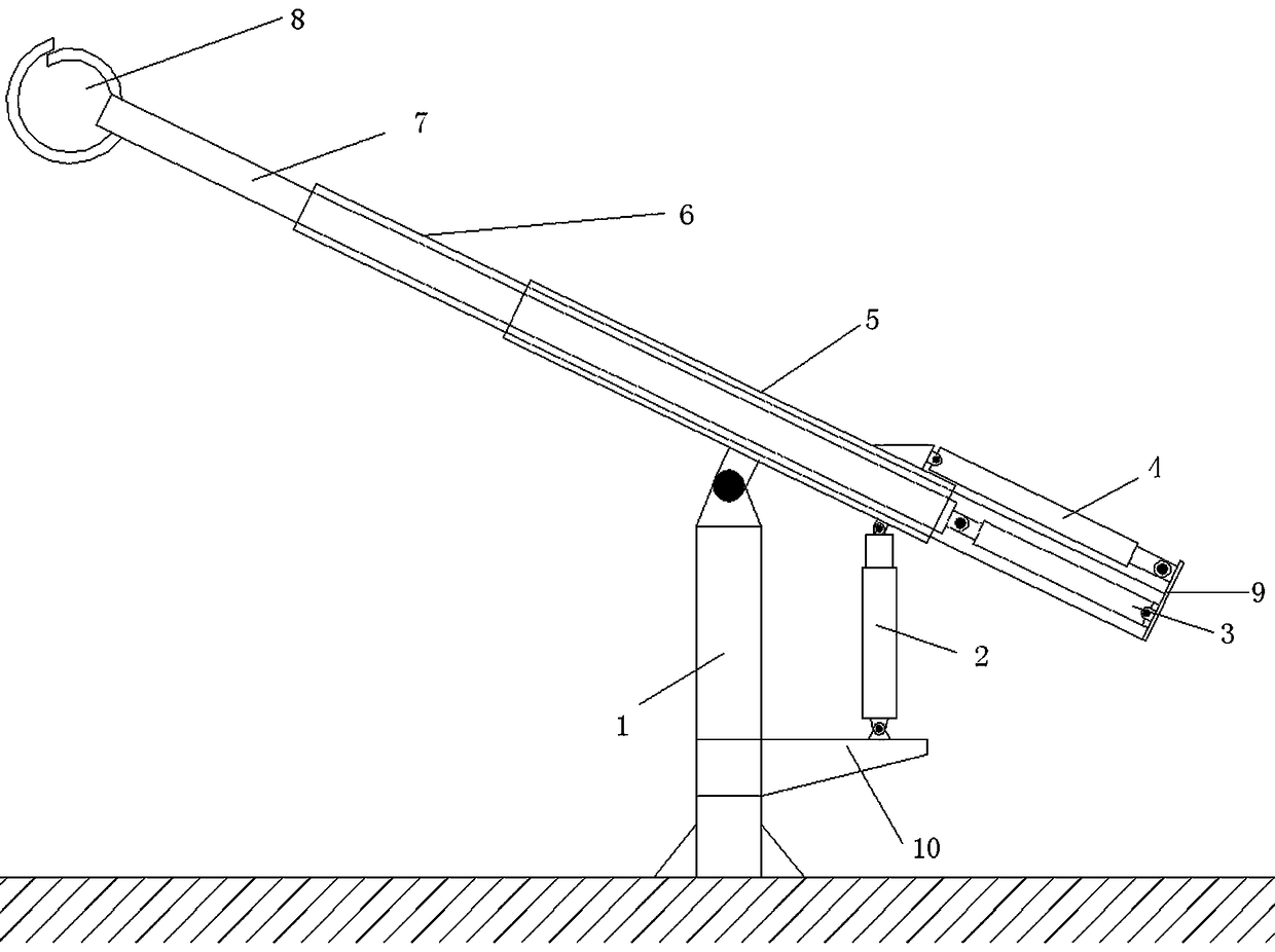
[0019] Such as figure 1 As shown, a telescopic lever lifting device includes an inner telescopic arm frame 7, an outer telescopic arm frame 6 is sheathed on the outer side of the inner telescopic arm frame 7, and an outermost telescopic sleeve is provided on the outer side of the outer telescopic arm frame 6. cylinder 5, one end of the inner telescopic boom 7 is connected with a spreader 8 for fixing lifting objects, the other end of the inner telescopic boom 7 is connected with one end of the second hydraulic cylinder 3 through a pin shaft, and the other end of the second hydraulic cylinder 3 passes through The opposite end of the outer telescopic boom spreader is connected with the fixing part 9 arranged at the opposite end of the outer telescopic boom spreader through a pin shaft, and the top of the opposite side of the outer telescopic boom spreader is connected with one end of the third hydraulic cylinder 4, and the third The other end of the hydraulic cylinder 4 is conne...

Embodiment 2

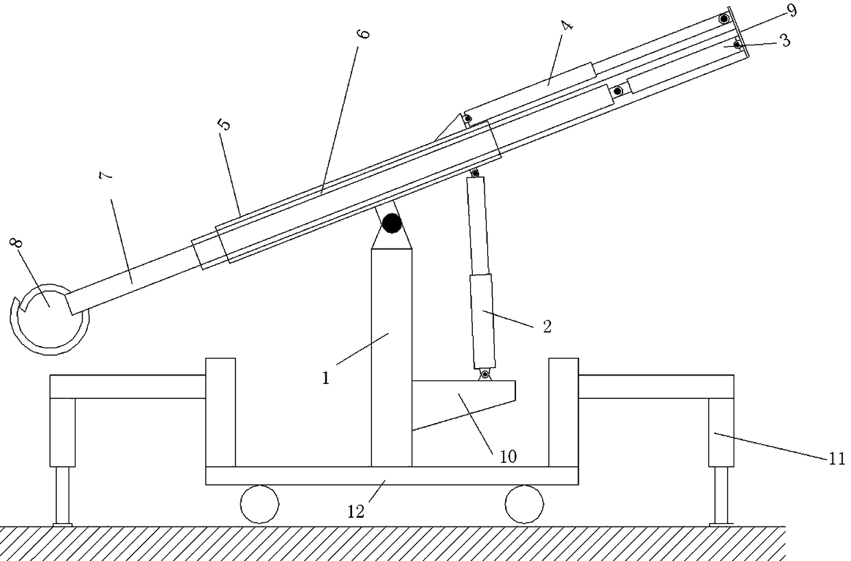
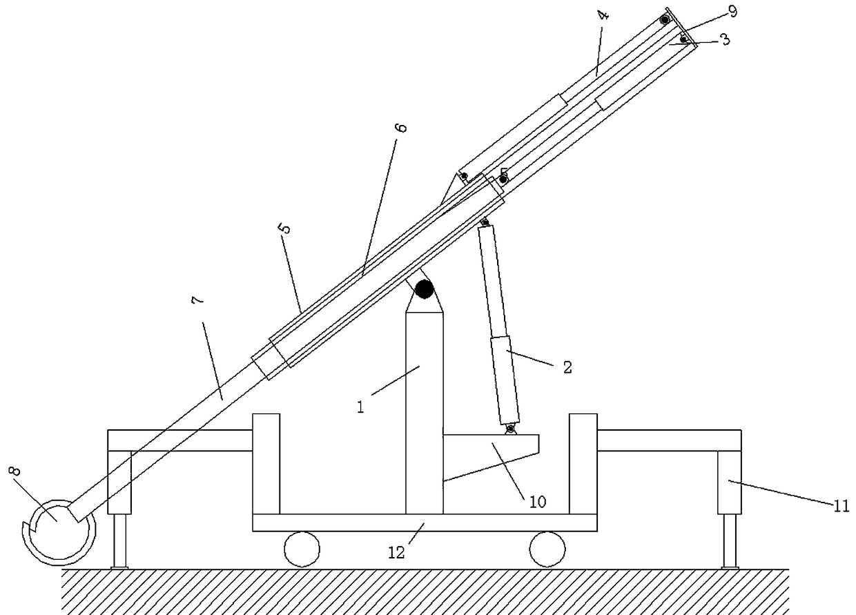
[0028] Such as figure 2 As shown, a telescopic lever lifting device includes an inner telescopic arm frame 7, an outer telescopic arm frame 6 is sheathed on the outer side of the inner telescopic arm frame 7, and an outermost telescopic sleeve is provided on the outer side of the outer telescopic arm frame 6. cylinder 5, one end of the inner telescopic boom 7 is connected with a spreader 8 for fixing lifting objects, the other end of the inner telescopic boom 7 is connected with one end of the second hydraulic cylinder 3 through a pin shaft, and the other end of the second hydraulic cylinder 3 passes through The opposite end of the outer telescopic boom spreader is connected with the fixing part 9 arranged at the opposite end of the outer telescopic boom spreader through a pin shaft, and the top of the opposite side of the outer telescopic boom spreader is connected with one end of the third hydraulic cylinder 4, and the third The other end of the hydraulic cylinder 4 is conn...


PUM


Abstract

The invention discloses telescopic lever hoisting equipment. The telescopic lever hoisting equipment adopts three-stage telescopic jib structure, wherein the telescopic sleeve on the outermost side isconnected with a hoisting column through a hinge pin, which is the sole fixed part in the jib system; the telescopic jib on the inner side is driven by a second hydraulic cylinder, the telescopic jibon the outer side is driven by a third hydraulic cylinder, a first hydraulic cylinder is connected with the telescopic sleeve on the outermost side through the hinge pin, and the inclination angle ofa telescopic lever structure is adjusted under driving of the first hydraulic cylinder, so that goods are ascended and descended. The telescopic lever hoisting equipment can be applied to almost allhoisting occasions, can be fixed on a certain work plane to serve as fixed hoisting equipment or can be used as movable hoisting equipment supported by certain movable equipment. The problem that large hoisting equipment cannot be carried and the goods are needed to be carried manually due to environmental space and other factors in the prior art are solved.

Description

technical field [0001] The invention relates to a lifting device, in particular to a retractable lever lifting device. Background technique [0002] Lifting equipment is electromechanical equipment used to carry or move heavy objects, mainly including lifting mechanism, operating mechanism, luffing mechanism, slewing mechanism and metal structure. The hoisting mechanism is the basic working mechanism of the crane. Most of them are composed of a suspension system and a winch. There are also hydraulic systems that lift heavy objects. Most of the suspension systems are suspended by wire ropes or slings. The operating mechanism is used to move heavy objects vertically and horizontally or adjust the working position of the crane, and is generally composed of a motor, a reducer, a brake and wheels. [0003] Existing lifting equipment usually has a huge structure and complex mechanism. For some very special workplaces, the environment is harsh and the working space is limited. Wor...

Claims


Application Information

Patent Timeline
Patent Type & Authority Applications(China)
IPC IPC(8): B66C25/00B66F15/00
Inventor 戚其松张延军白峭峰张森杜冬杰
Owner TAIYUAN UNIVERSITY OF SCIENCE AND TECHNOLOGY
Why Eureka
Try Eureka