
Mechanical arm mechanical lock and climbing device using mechanical arm mechanical lock

A technology of mechanical arms and mechanical locks, applied in the direction of lifting devices, can solve the problems of increased labor intensity of workers, impact on the safety and operability of climbing frames, and increased construction costs, so as to reduce labor intensity of workers and realize fully automatic operation. , the effect of saving labor costs

Active Publication Date: 2018-06-01
SHENZHEN TECHEN SCI & TECH CO LTD
View PDF5 Cites 0 Cited by
  • Summary
  • Abstract
  • Description
  • Claims
  • Application Information

AI Technical Summary

Problems solved by technology

Although the traditional mechanical lock structure of the mechanical arm realizes the automatic locking of the mechanical arm to a certain extent, it still needs to manually unlock the locked mechanical arm in the unlocking stage, which increases the labor intensity of the workers and increases the construction cost. reduce
In addition, the use of traditional electronic control methods to control the robotic arm has the disadvantages of complex wiring, difficult control, and high investment costs, and the construction environment of the climbing frame is poor, and it is often exposed to wind and rain in the natural environment. The line is damaged, which affects the reliability of its control of the robotic arm. Once the mechanical lock structure of the climbing frame mechanical arm fails, it will have a great impact on the overall safety and operability of the climbing frame, which will affect the entire project. construction progress

Method used


Image

  • Mechanical arm mechanical lock and climbing device using mechanical arm mechanical lock
  • Mechanical arm mechanical lock and climbing device using mechanical arm mechanical lock
  • Mechanical arm mechanical lock and climbing device using mechanical arm mechanical lock

Examples


Embodiment 1

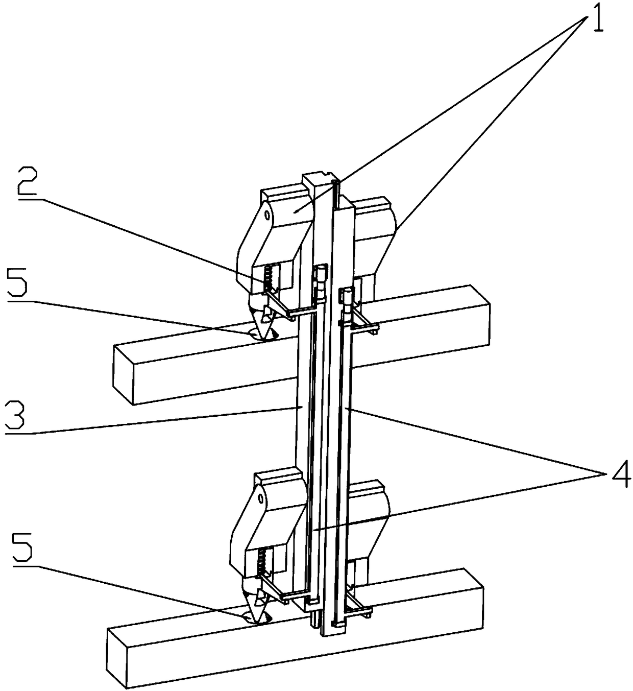
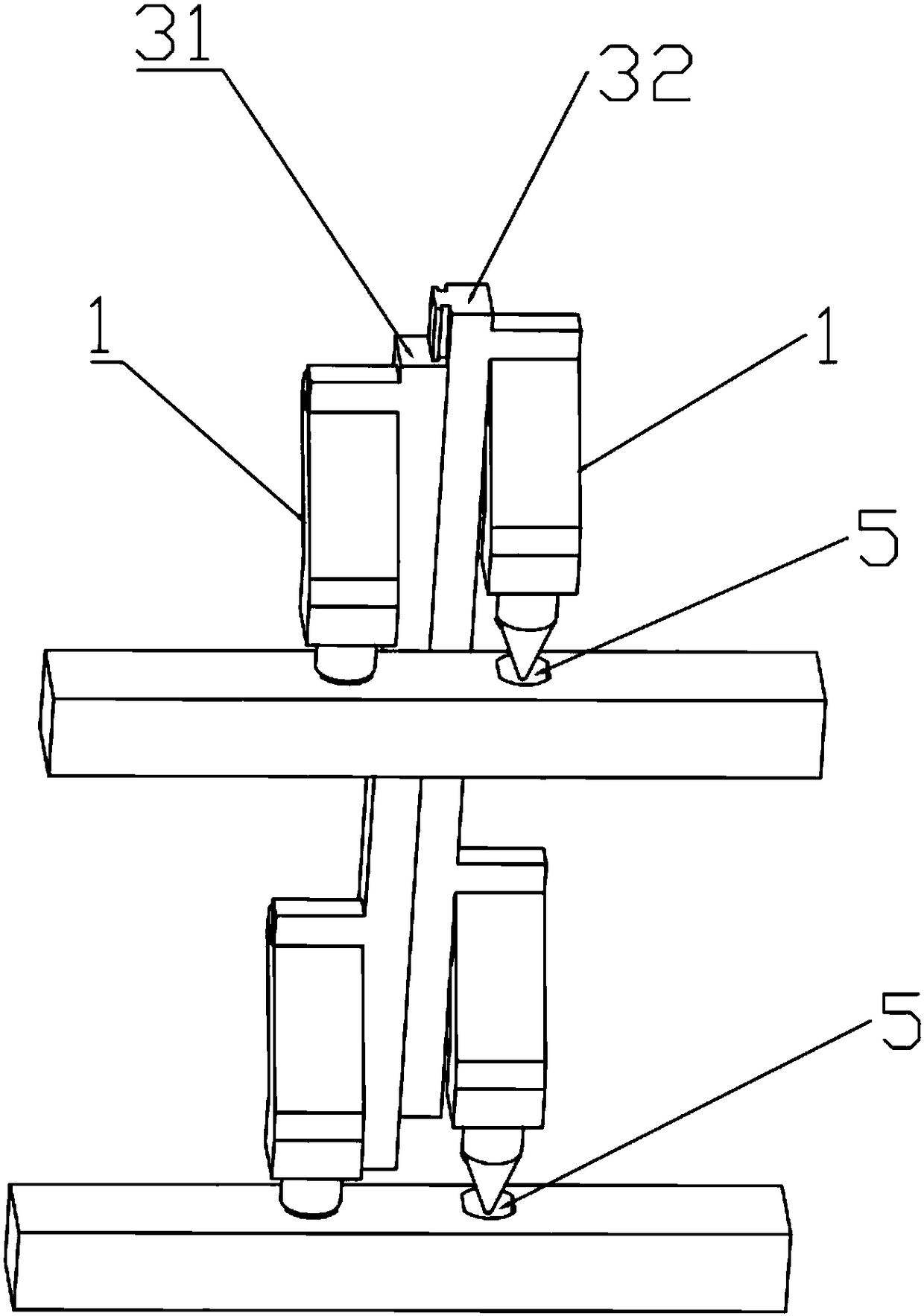
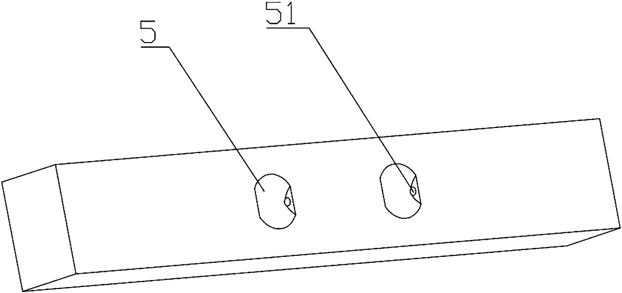
[0037] Such as figure 1As shown, the mechanical lock structure of the mechanical arm provided by the first embodiment of the present invention is used in the building climbing device, including the mechanical arm body 1 installed on the climbing device, the locking structure 2 installed on the mechanical arm body 1 and the setting The unlocking structure 4 on the climbing device is provided with a positioning hole 5 on the building; the locking structure 2 can be locked in the positioning hole 5 on the building, and the mechanical arm body 1 is locked at the same time; the unlocking structure 4 can lock the The structure 2 is unlocked from the positioning hole 5 on the building, and the mechanical arm body 1 is unlocked at the same time. The mechanical lock structure of the mechanical arm in this embodiment is installed on the guide rail 3 of the climbing frame. When it is in the locked state, the guide rail 3 and the climbing frame are locked as a whole. At this time, the ove...

Embodiment 2

[0043] Such as Figure 10 and Figure 11 As shown, the difference between the second embodiment and the first embodiment is that the lock cylinder 23 is connected to the lock body 21 in rotation. Specifically, such as Figure 12 As shown, the upper end of the lock body 21 is cylindrical, and the top is provided with an outwardly protruding ring 211, and the lower end of the lock body 21 is provided with a first displacement gap 336 that can accommodate the lock core 23. The first displacement gap The first through hole 332 is formed on the two side walls of 336 . Such as Figure 13 As shown, one end of the lock cylinder 23 is provided with a second avoidance gap 337, and the middle position of the second avoidance gap 337 is provided with a hollow cylinder 338 for installing the torsion spring 27, and the middle of the hollow cylinder 338 and the hollow cylinder 338 are in phase. A second through hole 333 communicating with the left and right is opened on the side wall of ...

Embodiment 3

[0046] Such as Figure 14 As shown, the third embodiment differs from the first embodiment in that the mechanical arm body 1 and the locking structure 2 in this embodiment are installed above the driving device 41, and the unlocking member 42 is a key on one end and the locking structure 2. 22 is fixedly connected, and the other end is fixedly connected to the stay cord of the driving device 41 . The driving device 41 can adopt a stepping motor, the motor rotates, and the pull cord shrinks, and at the same time drives the lock key 22 and the locking structure 2 to move down as a whole. When reaching the second position, the locking structure 2 can be unlocked. The mechanical arm body 1 and the locking structure 2 are provided with a plurality of guide rails 3, and the key 22 is provided with a guide hole for a drawstring to pass through, so that the drawstring can pass through the lock key 22 and the locking structure 2 located below. The lock keys 22 on the upper locking str...


PUM


Abstract

The invention relates to a mechanical arm mechanical lock structure and a climbing device using the mechanical arm mechanical lock structure. The mechanical arm mechanical lock structure comprises a mechanical arm body mounted on the climbing device, a locking structure arranged on the mechanical arm body and an unlocking structure arranged on the climbing device; the locking structure can be locked in the upper portion of a building, and the mechanical arm body can be locked; the unlocking structure can unlock the locking structure from the building, the mechanical arm body can be unlocked. The mechanical arm mechanical lock structure and the climbing device have the automatic locking and unlocking functions, the mechanical program type locking manner is adopted, the action is simple andreliable, the number of links is small, the manufacturing cost of a control system is greatly reduced, the structure is simple, use is convenient, full-automatic operation is achieved, labor intensityof workers is reduced, construction efficiency is greatly improved, and labor cost is saved.

Description

technical field [0001] The invention relates to the construction field, in particular to a mechanical lock of a mechanical arm and a climbing device using the mechanical lock of the mechanical arm. Background technique [0002] At present, in many high-rise construction lifting platforms, in order to ensure the safety of high-altitude operations, a large number of mechanical arms are used to fix and support the lifting platform. a puzzle. Although the traditional mechanical lock structure of the mechanical arm realizes the automatic locking of the mechanical arm to a certain extent, it still needs to manually unlock the locked mechanical arm in the unlocking stage, which increases the labor intensity of the workers and increases the construction cost. reduce. In addition, the use of traditional electronic control methods to control the robotic arm has the disadvantages of complex wiring, difficult control, and high investment costs, and the construction environment of the ...

Claims


Application Information

Patent Timeline
IPC IPC(8): B66F11/04B66F13/00
CPCB66F11/04B66F13/00B66F2700/09
Inventor 沈海晏吕光利张维贵
Owner SHENZHEN TECHEN SCI & TECH CO LTD
Learn More