Cloth printing and dyeing dehydrator device

一种脱水机、布料的技术,应用在处理纺织材料设备配置、用离心力液体/气体/蒸气去除等方向,能够解决无法水液循环利用、具有杂质、降低脱水机脱水效率等问题

Inactive Publication Date: 2018-06-01
SHANGHAI MAOBAI TRADING CO LTD
View PDF8 Cites 0 Cited by
  • Summary
  • Abstract
  • Description
  • Claims
  • Application Information

AI Technical Summary

Problems solved by technology

However, the above-mentioned structure has the following disadvantages: when the amount of water coming out of the dehydration bucket is large, the water will accumulate in the groove of the base, or even fill the groove, and the overloaded water will enter the dehydration bucket from the water outlet again. The cloth in the dehydration bucket is soaked again, which greatly reduces the dehydration efficiency of the dehydration machine
In addition, the drain outlet on the base of the existing dehydrator does not have a filter device, which makes the detached water contain impurities, making it impossible to recycle the water more effectively

Method used


Image

  • Cloth printing and dyeing dehydrator device
  • Cloth printing and dyeing dehydrator device
  • Cloth printing and dyeing dehydrator device

Examples


Embodiment Construction

[0021] The specific implementation manners of the present invention will be further described in detail below in conjunction with the accompanying drawings and embodiments. The following examples are used to illustrate the present invention, but are not intended to limit the scope of the present invention.

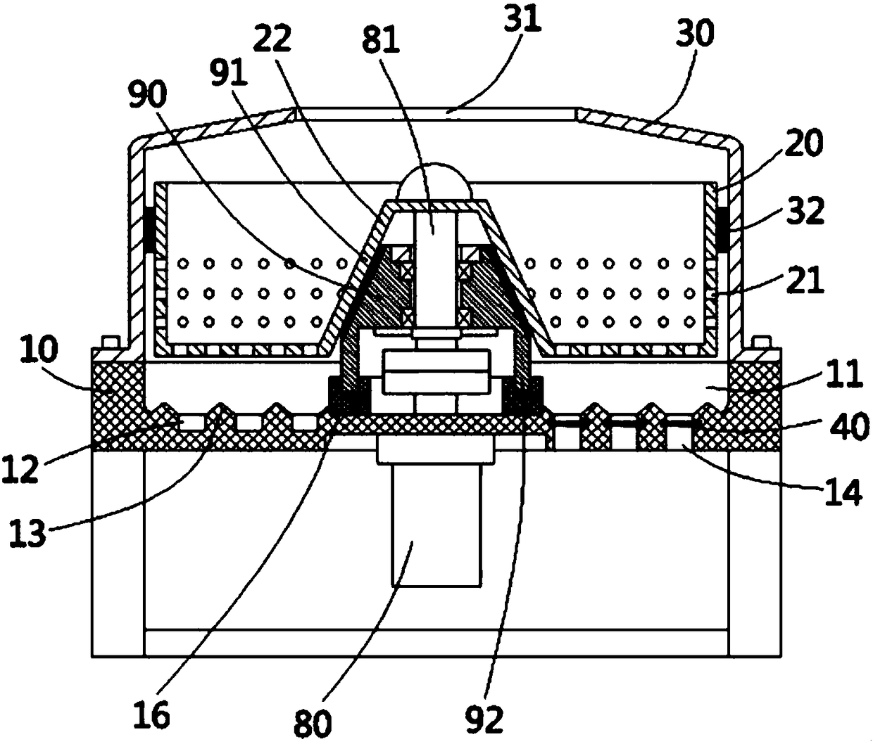
[0022] see figure 1 , a dehydrator device for printing and dyeing cloth according to the present invention, comprising a base 10, the top surface of the base has a groove 11, the groove is provided with a dehydration bucket 20, and the top surface of the base 10 is fixed There is a cylindrical protective cover 30, the top surface middle part of the cylindrical protective cover has a vertical placement through hole 31, the inner side wall of the cylindrical protective cover 30 is fixed with an annular wear ring 32, the dehydration bucket 20 is inserted into the annular wear-resistant ring 32 , the outer wall of the dehydration bucket 20 is close to the inner wall of the an...


PUM


Abstract

The invention discloses a cloth printing and dyeing dehydrator device which comprises a base. A groove is formed in the top face of the base, a dehydration barrel is arranged on the groove, a plurality of water outlets are formed in the dehydration barrel, and a plurality of annular water draining grooves are formed in the inner wall of the bottom of the groove; drainage openings are formed in theinner walls of the bottoms of the annular water draining grooves, a pair of oppositely-arranged plugging grooves are formed in the opposite side walls of each draining opening, a plugging block is fixedly connected to one end of a filter net, a plugging sleeve is arranged at the other end of the filter net, the plugging block and the plugging sleeve are plugged into the corresponding plugging grooves, the top face and the bottom face of the filter net are provided with a pair of connecting rods, guiding grooves are formed in the connecting rods, the upper end and the lower end of the pluggingsleeve is plugged into the guiding grooves in the corresponding connecting rods, one end of the filter net is plugged into the plugging sleeve, and a compression spring is fixedly connected between the end of the filter net and the inner wall of the plugging sleeve. The device has the advantages that water is not likely to be accumulated inside the groove of the base, the dehydration efficiency is improved, and dehydrated liquid can be filtered.

Description

[0001] This application is a divisional application with application number 2016103949065, an application date of June 3, 2016, and the title of the invention "a dehydrator device for printing and dyeing fabrics". technical field [0002] The invention relates to the technical field of textile machinery and equipment, in particular to a dehydrator device for printing and dyeing cloth. Background technique [0003] The existing dehydrator for printing and dyeing fabrics throws out the moisture in the fabric, and then discharges the water through the water outlet hole on the dehydration bucket. The discharged water is temporarily buffered in the groove of the base, and then discharged through the drain on the base. Dehydrator. However, the above-mentioned structure has the following disadvantages: when the amount of water coming out of the dehydration bucket is large, the water will accumulate in the groove of the base, or even fill the groove, and the overloaded water will en...

Claims


Application Information

Patent Timeline
Patent Type & Authority Applications(China)
IPC IPC(8): D06B15/10D06B23/20
CPCD06B15/10D06B23/20
Inventor 不公告发明人
Owner SHANGHAI MAOBAI TRADING CO LTD
Why Eureka
Try Eureka