Simply assembled and disassembled pipeline connecting piece

A connection piece, a simple technology, applied in the direction of pipe/pipe joint/fitting, sleeve/socket connection, passing components, etc., can solve the installation requirements of scientific installation process, no qualitative improvement in operability, and direct push connection structure High, stainless steel pipe use cost increases, etc., to achieve the effect of simplifying the installation and operation process, stable fixing effect, and wide application in the installation environment

Pending Publication Date: 2018-06-01
广东粤华不锈钢型材股份有限公司
View PDF7 Cites 5 Cited by
  • Summary
  • Abstract
  • Description
  • Claims
  • Application Information

AI Technical Summary

Problems solved by technology

In construction practice, the stainless steel piping system produced by the traditional connection method has the problems of complicated construction technology and high installation space requirements; some connections need to use sealing materials, which increases the source of pollution
For example, the compression connection requires the use of a special compression device and ample operating space to ensure the firmness after pressing; the threaded connection also needs to reserve enough space for operation with a wrench, and when both ends of the pipe are threaded. It will become more difficult to disassemble and replace; the direct push connection structure has the disadvantages of high installation requirements, easy leakage when the operation is not in place, and inability to disassemble when both ends are direct push connection structures
Above all, various defects increase the use cost of stainless steel pipes and limit the scope of use. Although those skilled in the art have made some modifications to the pipe connection structure, it is more to enhance the sealing performance and connection stability. For installation There is no qualitative improvement in the science and operability of the process

Method used


Image

  • Simply assembled and disassembled pipeline connecting piece
  • Simply assembled and disassembled pipeline connecting piece
  • Simply assembled and disassembled pipeline connecting piece

Examples


Embodiment 1

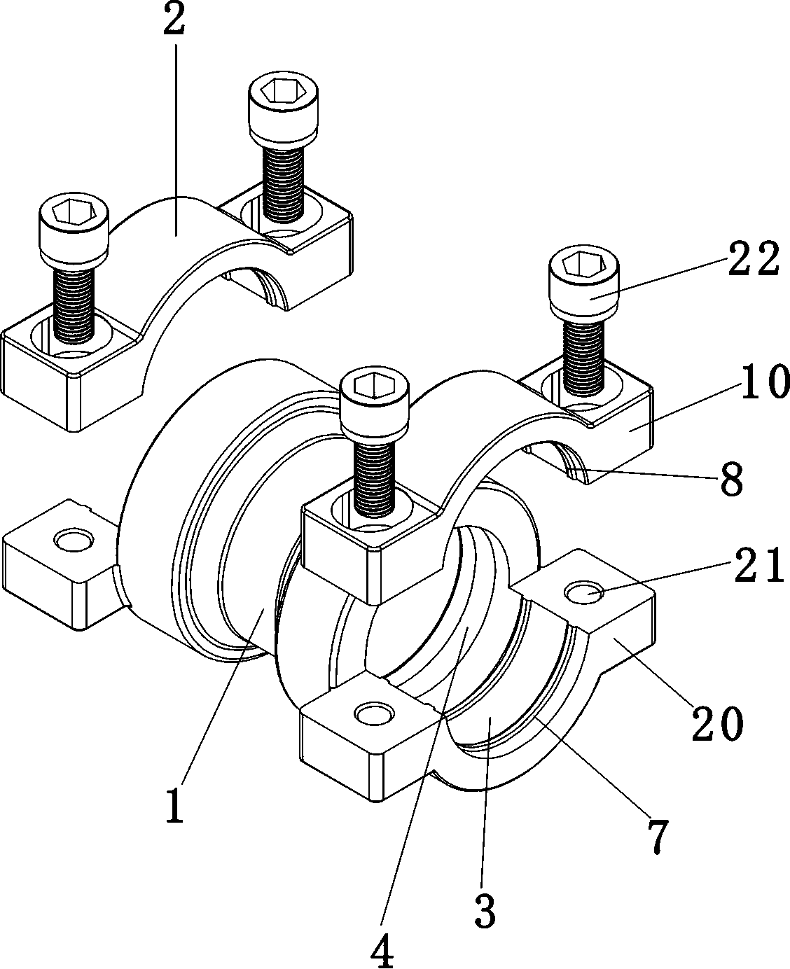
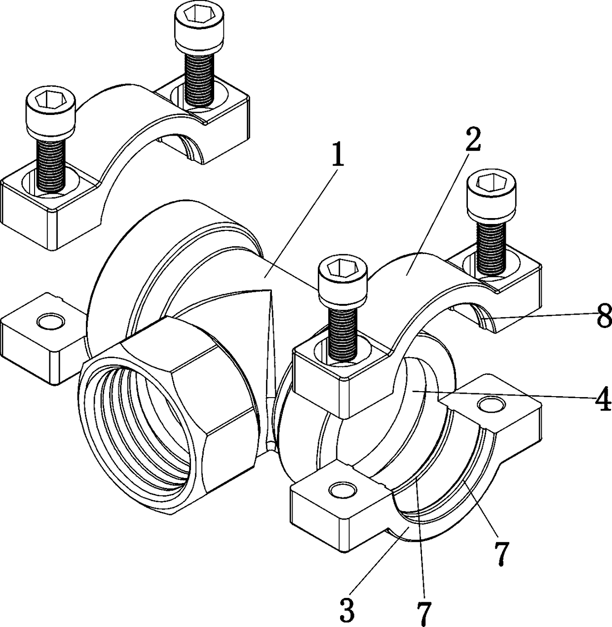
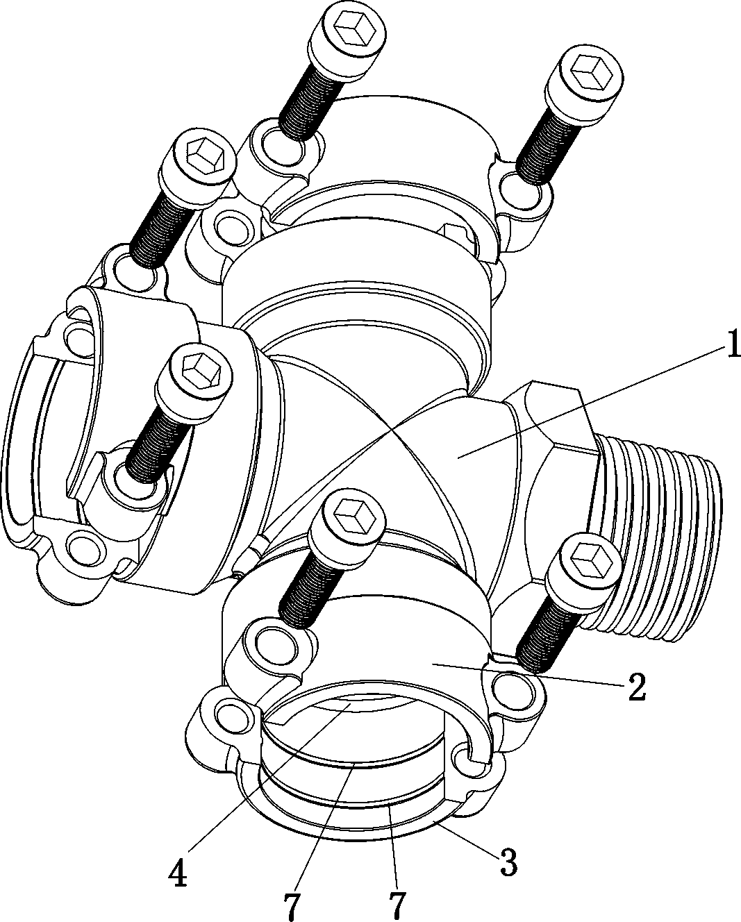
[0031]A set of connector series products for stainless steel pipes, including straight through, 45º elbow, 90º elbow, tee, cross, and various forms of variable diameter pipe products, etc. The structure of each product includes the joint body 1, the pipe Ferrule piece 2. as attached figure 1 , attached figure 2 , attached image 3 And attached Figure 4 As shown, the joint body 1 is a hollow structure, and at least one opening is a circular insertion opening, which extends outwards at the insertion opening to form a semi-circular sleeve portion 3 . Other openings of the joint body can be the same embedded openings, or threaded joints with external thread structure or internal thread structure. figure 2 , attached image 3 And attached Figure 4 Structure.

[0032] A first sealing groove 4 is formed on the inner wall surface of the joint body close to the sleeve portion, for embedding a first sealing ring 5 of elastic material. The shape of the sealing ring is as atta...

Embodiment 2

[0036] A stainless steel pipe connecting flange, as attached Figure 8 As shown, it is composed of a flange 30 and a joint 31 , the inner wall of the joint 31 is formed with a first sealing groove 311 , and the first sealing ring is installed; Two parallel raised ribbed rings 321 are formed on the inner wall of the sleeve part, and two ear parts are formed on the outer side and at the diameter position, each ear part is pierced with a mounting hole 33 . A semi-annular pipe sleeve hoop piece 34 also forms two parallel raised ribbed rings 341, forming a closed ring structure with the raised ribbed rings 321 of the pipe sleeve portion. Tube ferrule pieces are also attached to the ears, creating mounting through-holes 35 .

[0037] When the connecting flange of this embodiment is used, the pipe to be connected is inserted into the flange joint and inside the first sealing ring. Then the pipe sleeve hoop piece is set on the pipe sleeve part, the connected pipe is clamped, and the...

Embodiment 3

[0039] A pipe cap for stainless steel pipes, as attached Figure 9 As shown, it is composed of a cap body 40 and a tube sleeve hoop piece 41 , the cap body is cylindrical, one end of which is closed, and the other end extends outward, forming a semi-circular tube sleeve portion 42 . The pipe sleeve hoop piece 41 is also semi-circular, and is installed on the pipe sleeve portion to form a cylindrical pipe sleeve structure. Both the pipe sleeve part and the pipe sleeve hoop piece are connected to the ear part 43, and are formed with mounting holes, which are inserted and fastened by bolts 44. The structure of the first sealing groove and ribs on the inner wall of the cap is the same as that of Example 1, see the attached figure 1 To attach Figure 4 shown.

[0040] The pipe cap of this embodiment is fitted to the end of the pipe to close the pipe. The basic operation of the installation and use method is the same as that of Embodiment 1, please refer to the description of Em...


PUM


Abstract

The invention discloses a simply assembled and disassembled pipeline connecting piece. The simply assembled and disassembled pipeline connecting piece comprises an integrally formed join body of a hollow structure, wherein the joint body has a round embedding opening. A first seal groove is formed in the inner side of the embedding opening to embed a first seal ring; the joint body extends outwardat the embedding opening to form a semi-annular pipe sleeve part; a semi-annular pipe sleeve hoop piece is mounted on the pipe sleeve part to form a cylindrical pipe sleeve structure to clamp and sleeve a connected pipeline tightly; rib-line bumps can be formed on the inner wall surfaces of the pipe sleeve part and the pipe sleeve hoop piece and a second seal groove and/or a banding annular groove can be also formed on the inner wall surfaces of the pipe sleeve part and the pipe sleeve hoop piece to mount a second seal ring and/or a banding ring; and the outer side of the wall body is separately connected to at least two lug parts to form a mounting hole, an inner thread may be arranged on the smooth inner wall, a fastening bolt is sleeved in the mounting hole to connect the pipe sleeve hoop piece to the pipe sleeve part.

Description

technical field [0001] The invention belongs to the field of fluid pipeline products, in particular to pipeline connectors for connecting pipe pieces to form a pipe network. Background technique [0002] Pipeline connection is the core process of forming a pipe network. The traditional pipe connection method varies according to the pipe material. The thread connection method used by metal pipes has the longest history. Some metal pipes adopt compression connection, PVC and other plastics and Composite material pipes are mostly heat-sealed. For stainless steel pipe connections that are becoming more and more widely used, in addition to the compression connection and threaded interface connection, some products adopt a direct push connection structure, and the connection of the pipe fittings is realized by locking the connected pipe fittings through the locking piece in the connector. [0003] Due to its excellent corrosion resistance, weather resistance, and clean performanc...

Claims


Application Information

Patent Timeline
Patent Type & Authority Applications(China)
IPC IPC(8): F16L21/06F16J15/06
CPCF16J15/022F16J15/06F16L21/065
Inventor 林树灿
Owner 广东粤华不锈钢型材股份有限公司
Why Eureka
Try Eureka