
Two-disk proportional tunnel kiln control heating pipe

A technology for controlling tunnels and heating pipes, which is applied in lighting and heating equipment, gas fuel burners, and combustion methods. Even heating effect

Pending Publication Date: 2018-06-01
佛山市顺德区奥利焙食品机械有限公司
View PDF0 Cites 0 Cited by
  • Summary
  • Abstract
  • Description
  • Claims
  • Application Information

AI Technical Summary

Problems solved by technology

Due to the problem of temperature shock, the traditional fire tube heating method makes the temperature unable to be accurately controlled, and it is difficult to meet the products with high requirements for baking temperature control.
[0003] At present, the heating system of the tunnel furnace is mainly direct-fired, that is, it is heated by burning fire tubes. There are upper and lower rows of fire tubes in the inner chamber. The traditional direct-fired fire tube heating has only two forms—— Combustion and extinguishing, there are certain defects in temperature control, mainly manifested in that when the inner chamber does not reach the set area temperature, the fire tube in this area will always be heated with the maximum firepower, and when the set temperature is reached, the fire tube will immediately At this time, because the fire tube has a very large waste heat, there is a certain temperature shock in this area. When the actual temperature is lower than the set temperature, the fire tube is re-ignited and heated. The fire tubes work alternately in this way, because the existence of the temperature shock makes The temperature cannot be precisely controlled

Method used


Image

  • Two-disk proportional tunnel kiln control heating pipe
  • Two-disk proportional tunnel kiln control heating pipe
  • Two-disk proportional tunnel kiln control heating pipe

Examples


Embodiment Construction

[0017] The following will clearly and completely describe the technical solutions in the embodiments of the present invention with reference to the accompanying drawings in the embodiments of the present invention. Obviously, the described embodiments are only some, not all, embodiments of the present invention. Based on the embodiments of the present invention, all other embodiments obtained by persons of ordinary skill in the art without making creative efforts belong to the protection scope of the present invention.

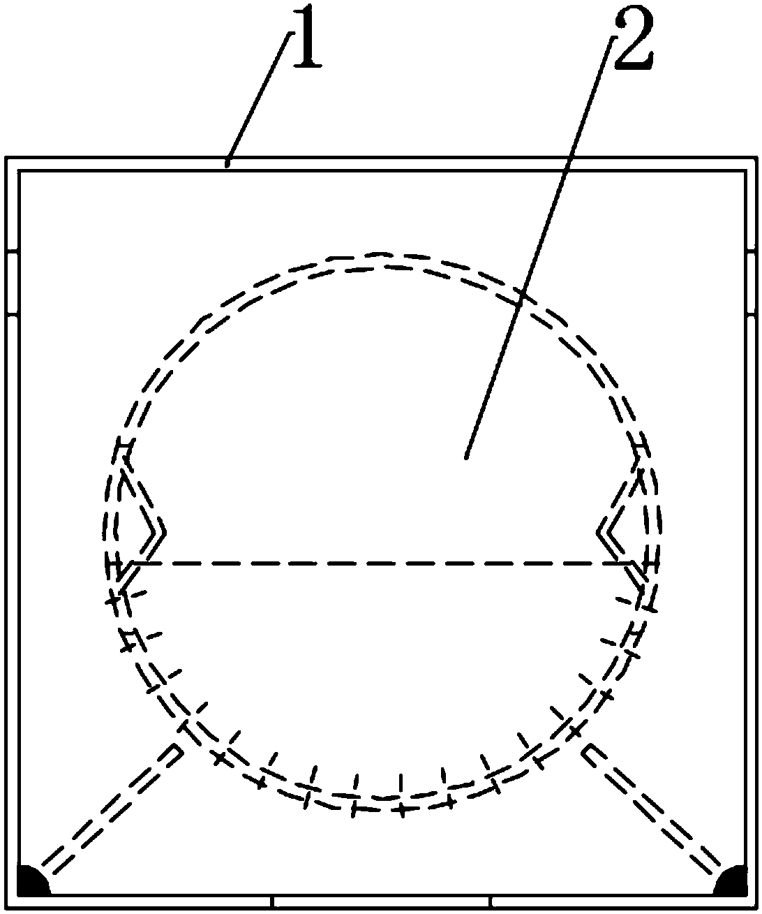
[0018] see Figure 1~4 , in an embodiment of the present invention, a heating tube for a two-disc proportional control tunnel furnace includes a mixing air duct 1, a combustion tube 2, and a burner installation port 5; the mixing air duct 1 is made of 304 stainless steel, and the mixing air duct 1 is made of 304 stainless steel. A row of small heat outlets 7 of φ10 are arranged on the front and rear sides of the air duct 1, and a row of main heat outlets 6 of ...


PUM


Abstract

The invention discloses a two-disk proportional tunnel kiln control heating pipe. The two-disk proportional tunnel kiln control heating pipe comprises a mixed air hose, a combustion tube and a nozzleinstallation opening. The upper portion of the front surface and the upper portion of the back surface of the mixed air hose are each provided with a row of small heat air openings. A row of main heatair outlets are formed in the lower portion of the mixed air hose. The combustion tube is installed inside the mixed air hose. The middle of the front side and the middle of the back side of the combustion tube are each provided with a row of circular holes. The right end of the combustion tube abuts against the left side of a rubber asbestos pad, and the right side of the rubber asbestos pad abuts against the nozzle installation opening. The sizes of flames can be controlled by adjusting the proportion of fuel gas and air, the flames can be kept to fluctuate within a small range, and the temperature impact problem can be well solved; and the flames cannot extinguish in the process, heat is evenly distributed into an inner bore through the small heat air openings and the main heat air outlets in the surface of the mixed air hose, the same cross section in the inner bore can obtain heat approaching as much as possible, and thus baked products can be evenly heated to the greatest extent.

Description

technical field [0001] The invention relates to a temperature distribution device, in particular to a heating tube of a two-disc proportional control tunnel furnace. Background technique [0002] As people's living conditions get better and better, people's requirements for the quality of baked products are getting higher and higher. In addition to good taste, they also need good taste, exquisite appearance, etc., and the appearance is largely It depends on the quality of the baking temperature. The traditional fire tube heating method cannot precisely control the temperature due to the problem of temperature shock, and it is difficult to meet the requirements of high baking temperature control products. [0003] At present, the heating system of the tunnel furnace is mainly direct-fired, that is, it is heated by burning fire tubes. There are upper and lower rows of fire tubes in the inner chamber. The traditional direct-fired fire tube heating has only two forms—— Combust...

Claims


Application Information

Patent Timeline
Patent Type & Authority Applications(China)
IPC IPC(8): F23D14/02F23D14/58
CPCF23D14/02F23D14/586
Inventor 梁海杰
Owner 佛山市顺德区奥利焙食品机械有限公司
Learn More