High power LED drive circuit with emergency function

A technology of LED drive and emergency function, which is applied in the direction of emergency power supply arrangement, circuit device, lamp circuit layout, etc., can solve the problem of complex switching circuit, achieve the effect of simple circuit and guaranteed standby working time

Inactive Publication Date: 2013-08-07
OCEANS KING LIGHTING SCI&TECH CO LTD +1
View PDF2 Cites 0 Cited by
  • Summary
  • Abstract
  • Description
  • Claims
  • Application Information

AI Technical Summary

Problems solved by technology

[0004] The technical problem to be solved by the present invention is to provide a high-power LED drive circuit with an emergency function in view of the defect of the complex switching circuit between the commercial power and the storage battery in the prior art LED drive circuit

Method used


Image

  • High power LED drive circuit with emergency function
  • High power LED drive circuit with emergency function

Examples


Embodiment Construction

[0026] In order to make the object, technical solution and advantages of the present invention clearer, the present invention will be further described in detail below in conjunction with the accompanying drawings and embodiments.

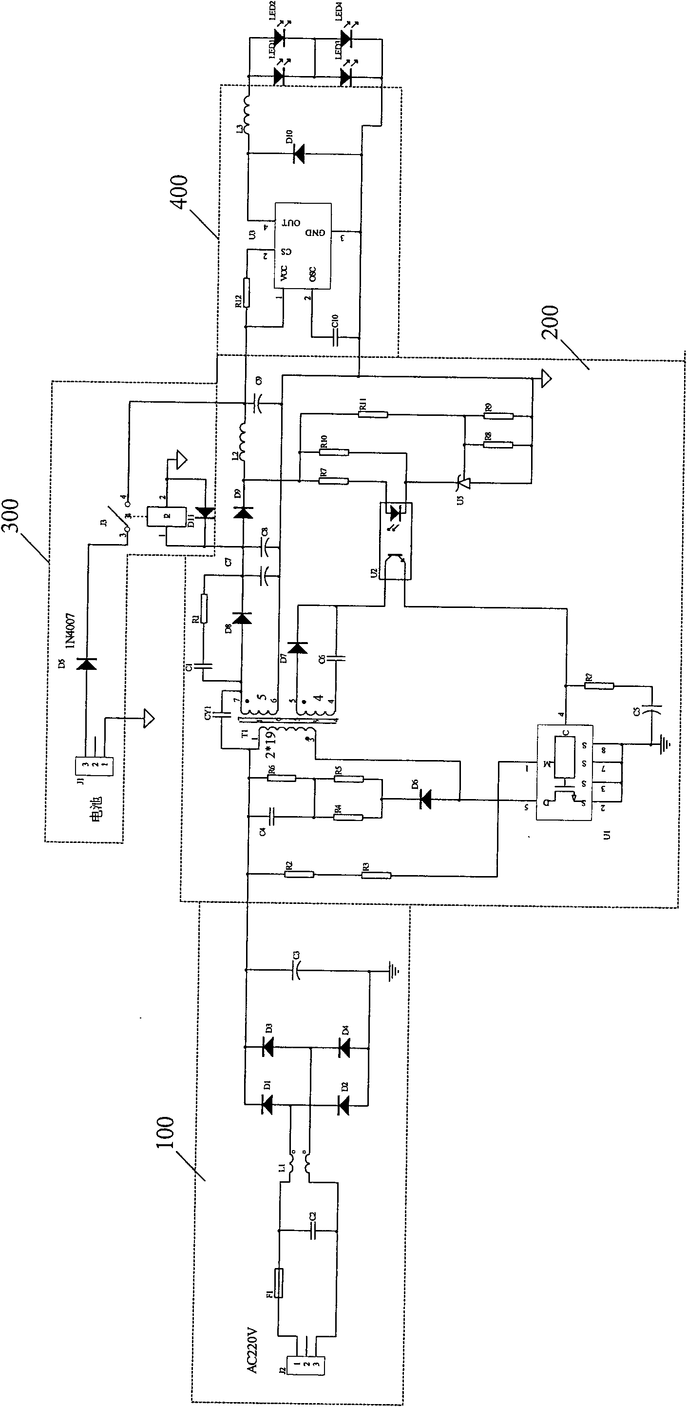
[0027] see figure 1 , is a schematic structural diagram of a high-power LED driving circuit with an emergency function in a preferred embodiment of the present invention. Such as figure 1 As shown, the high-power LED drive circuit with emergency function provided by the present invention includes a rectification and filtering unit 100 , a flyback unit 200 , a constant current drive unit 400 and an emergency unit 300 . Wherein, the rectification and filtering unit 100 is connected to the input end of the LED driving circuit, and is used for rectifying and filtering the input AC signal. The flyback unit 200 is connected to the rectification and filtering unit 100 and is used for performing PWM wave modulation according to load conversion. The cons...


PUM


Abstract

The invention relates to a high power LED drive circuit with the emergency function, comprising a rectifying and filtering unit, a reverse excitation unit, a constant current driving unit and an emergency unit, wherein the rectifying and filtering unit is connected with the input end of the LED drive circuit and is used for rectifying and filtering the input alternating current signals; the reverse excitation unit is connected with the rectifying and filtering unit and is used for PWM wave modulation according to load change; the constant current driving unit is connected with the reverse excitation unit and is used for driving the LED to work at constant current; and the emergency unit is connected with the reverse excitation unit and provides power to the constant current driving unit when no alternating current input is detected by detecting the current of the reverse excitation unit. The LED drive circuit is simple and can automatically switch to the emergency power supply so as not to go out even though the mains supply has failure. The leakage current of the cells in the circuit is almost zero, thus ensuring the standby working time of the cells.

Description

technical field [0001] The present invention relates to an LED drive circuit, more specifically, to a high-power LED drive circuit with emergency function. Background technique [0002] For special lamps with batteries, it is necessary to design a circuit to switch between mains and batteries. The usual switching circuit is relatively complex in design. The invention patent with the application number of 200810061210.6 "A Circuit of LED Lighting Lamp and LED Light Using the Circuit" discloses a circuit of LED lighting emergency lights. The circuit starts the emergency circuit through the power failure identification circuit, and uses a single-pole switch as the switching circuit. The added circuit identification circuit of the circuit has complex design, reduces reliability and increases power consumption. Another example is the utility model patent "Emergency Power Supply for Cordless Telephones" whose application number is 94207217.0, which uses a relay to control the w...

Claims


Application Information

Patent Timeline
Patent Type & Authority Patents(China)
IPC IPC(8): H05B37/02H02M7/08H02M1/14H02J9/06
CPCY02B70/16Y02B20/42Y02B20/40Y02B70/10Y02B70/30Y04S20/20
Inventor 周明杰李万丰
Owner OCEANS KING LIGHTING SCI&TECH CO LTD
Why Eureka
Try Eureka