Eureka AIR delivers breakthrough ideas for toughest innovation challenges, trusted by R&D personnel around the world.

An adjustable optical isolator and its adjustment method

A technology of optical isolator and adjustment method, applied in the field of optical fiber communication, can solve cumbersome problems and achieve the effect of simple adjustment method

Active Publication Date: 2019-09-13
XIAMEN SIKETU OPTOELECTRONICS TECH CO LTD
View PDF4 Cites 0 Cited by
  • Summary
  • Abstract
  • Description
  • Claims
  • Application Information

AI Technical Summary

Problems solved by technology

However, the current optical isolator cannot change the optical transmission direction after installation, and in some experimental places, the transmission direction needs to be changed continuously, which requires frequent loading and unloading of the optical isolator, which is very cumbersome

Method used


Image

  • An adjustable optical isolator and its adjustment method
  • An adjustable optical isolator and its adjustment method

Examples


Embodiment Construction

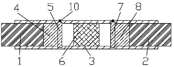
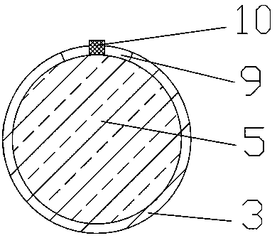
[0018] Combine below Figure 1-2 The present invention is further described, but the protection scope of the present invention is not limited to the content.

[0019] Wherein the same components are denoted by the same reference numerals. It should be noted that the words "front", "rear", "left", "right", "upper" and "lower" used in the following description refer to the directions in the drawings, and the words "inner" and "outer "respectively refer to directions toward or away from the geometric center of a specific component, and the drawings are all in a very simplified form and use inaccurate ratios, which are only used to facilitate and clearly assist the purpose of illustrating the embodiments of the present invention.

[0020] For the sake of clarity, not all features of an actual embodiment are described. In the following description, well-known functions and constructions are not described in detail since they would obscure the invention with unnecessary detail and ...


PUM


Abstract

The invention discloses an adjustable optical isolator and an adjusting mode thereof. The adjustable optical isolator comprises an incident collimator, an emergent collimator and a shell. The incidentcollimator is inserted into the left end of the shell. The emergent collimator is inserted into the right end of the shell. A first lens is arranged at the right end of the incident collimator, and afirst polarizer is arranged at the right end of the first lens. A faraday rotator is arranged at the right end of the first polarizer. A second polarizer is arranged at the right end of the faraday rotator. A second lens is arranged at the right end of the second polarizer. According to the invention, a hand-rotating head can be operated to enable each polarizer to rotate within 0-45 degrees, sothat the purpose of changing the light transmission direction of the optical isolator is realized. When the hand-rotating head of the first polarizer is at a 0-degree position and the hand-rotating head of the second polarizer is at a 45-degree position, the light can be transmitted from left to right. When the hand-rotating head of the second polarizer is at a 0-degree position and the hand-rotating head of the first polarizer is at a 45-degree position, the light can be transmitted from right to the left. The adjusting mode is simple.

Description

technical field [0001] The invention relates to an adjustable optical isolator and its adjustment method, belonging to the technical field of optical fiber communication. Background technique [0002] Semiconductor lasers are very sensitive to reflected light, and reflected light causes instability in the performance of semiconductor lasers. Therefore, it is necessary to integrate miniaturized optical isolators in semiconductor laser devices. The existing optical isolator consists of a unidirectional Faraday rotator and the first and second polarizers located on both sides of the Faraday rotator, which mainly use the Faraday effect of magneto-optic crystals to allow light to pass in one direction and prevent Pass in the opposite direction to prevent the adverse effects of post-transmission in the optical path on the light source and the optical path system due to various reasons. However, the current optical isolator cannot change the optical transmission direction after in...

Claims


Application Information

Patent Timeline
Patent Type & Authority Patents(China)
IPC IPC(8): H01S5/06G02B6/27
Inventor 沈庆元
Owner XIAMEN SIKETU OPTOELECTRONICS TECH CO LTD
Why Eureka
Eureka Blog
Learn More