
Photovoltaic power generation system installation structure applied to roof with steel-frame structure

A photovoltaic power generation system and installation structure technology, applied in the direction of photovoltaic power generation, photovoltaic modules, photovoltaic module support structures, etc., can solve the problems of inability to apply photovoltaic panels of different specifications, inability to protect photovoltaic panels, and large use limitations, and achieve Increase the use range, facilitate automatic reset, and prolong the service life

Inactive Publication Date: 2018-06-01
苏州绿萃筑信息科技有限公司
View PDF0 Cites 6 Cited by
  • Summary
  • Abstract
  • Description
  • Claims
  • Application Information

AI Technical Summary

Problems solved by technology

[0002] The installation structure of the photovoltaic power generation system in the prior art cannot be applied to the installation of photovoltaic panels of different specifications, the use is limited, and the operation is inconvenient; the installation structure of the photovoltaic power generation system in the prior art cannot protect the photovoltaic panels, which is very easy to cause Photovoltaic panels are damaged and maintenance costs are high, so there is an urgent need for a photovoltaic power generation system installation structure for steel frame structure roofs to solve the above problems

Method used


Image

  • Photovoltaic power generation system installation structure applied to roof with steel-frame structure
  • Photovoltaic power generation system installation structure applied to roof with steel-frame structure
  • Photovoltaic power generation system installation structure applied to roof with steel-frame structure

Examples


specific Embodiment approach

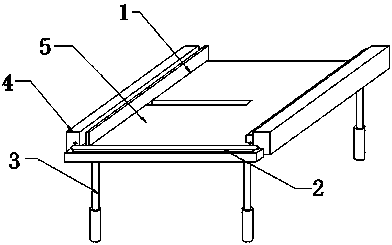
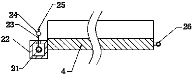
[0023] Specific implementation method: when in use, the operator first pulls the pressing block 14 upward, and the pressing block 14 drives the push plate 12 to move upward in the guide groove 11, and the push plate 12 moves to squeeze the spring 13, causing the spring 13 to elastically deform, and then the photovoltaic The board is placed in the card slot 5, and the right end surface of the photovoltaic panel is closely attached to the right side of the card slot 5, and then the pressure block 14 is sent away, and the spring 13 pushes the push plate 12 to move downward under the action of the resilience force. The push plate 12 moves downward to drive the pressure block 14 to move downward, and then the pressure block 14 is closely attached to the photovoltaic panel, and then the motor is run, and the motor drives the screw rod 17 to rotate in the groove 18, and the ball nut pair controls the rotation of the screw rod 17 The motion is converted into linear motion, the nut seat...


PUM


Abstract

The invention provides a photovoltaic power generation system installation structure applied to a roof with a steel-frame structure. The structure comprises a spring, a nut base, a pressing plate, a lead screw, a bunching roller, rain shade cloth, a pothook and a clamping ring, wherein the spring is installed at the upper part position in a guiding slot, the lower end of the spring is connected with a push plate, the nut base is installed on the lead screw, the pressing plate is fixed on the upper face of the nut base, and the lead screw is installed in a groove. Due to such design, the quickinstallation function of a photovoltaic panel is achieved, the application range of the device is increased, the bunching roller is installed at the middle part position in a box, the lower end of therain shade cloth warps the annular side surface of the bunching roller, the upper end of the rain shade cloth is connected with a limiting rod, the pothook is installed on the limiting rod, the clamping ring is fixed on the rear end face of a support, the protection function of the photovoltaic panel is achieved, and the service life of the photovoltaic panel is prolonged; the photovoltaic powergeneration system installation structure is reasonable in structure, wide in application range, convenient to operate and long in service life.

Description

technical field [0001] The invention relates to a photovoltaic power generation system installation structure for a steel frame structure roof, belonging to the field of solar energy equipment. Background technique [0002] The installation structure of the photovoltaic power generation system in the prior art cannot be applied to the installation of photovoltaic panels of different specifications, the use is limited, and the operation is inconvenient; the installation structure of the photovoltaic power generation system in the prior art cannot protect the photovoltaic panels, which is very easy to cause The damage of photovoltaic panels leads to high maintenance costs, so there is an urgent need for a photovoltaic power generation system installation structure for steel frame structure roofs to solve the above problems. Contents of the invention [0003] Aiming at the deficiencies in the prior art, the object of the present invention is to provide a photovoltaic power ge...

Claims


Application Information

Patent Timeline
Patent Type & Authority Applications(China)
IPC IPC(8): H02S20/23H02S40/00
CPCH02S20/23H02S40/00Y02B10/10Y02E10/50
Inventor 任学文张宇
Owner 苏州绿萃筑信息科技有限公司
Learn More