

Indication method, base station and terminal of reference signal configuration information
A technology of reference signal and sounding reference signal, which is applied to base stations and terminals, and the indication field of reference signal configuration information, to achieve the effect of reducing the overhead of the physical layer
- Summary
- Abstract
- Description
- Claims
- Application Information
AI Technical Summary
Problems solved by technology
Method used
Image

Examples
Embodiment 1
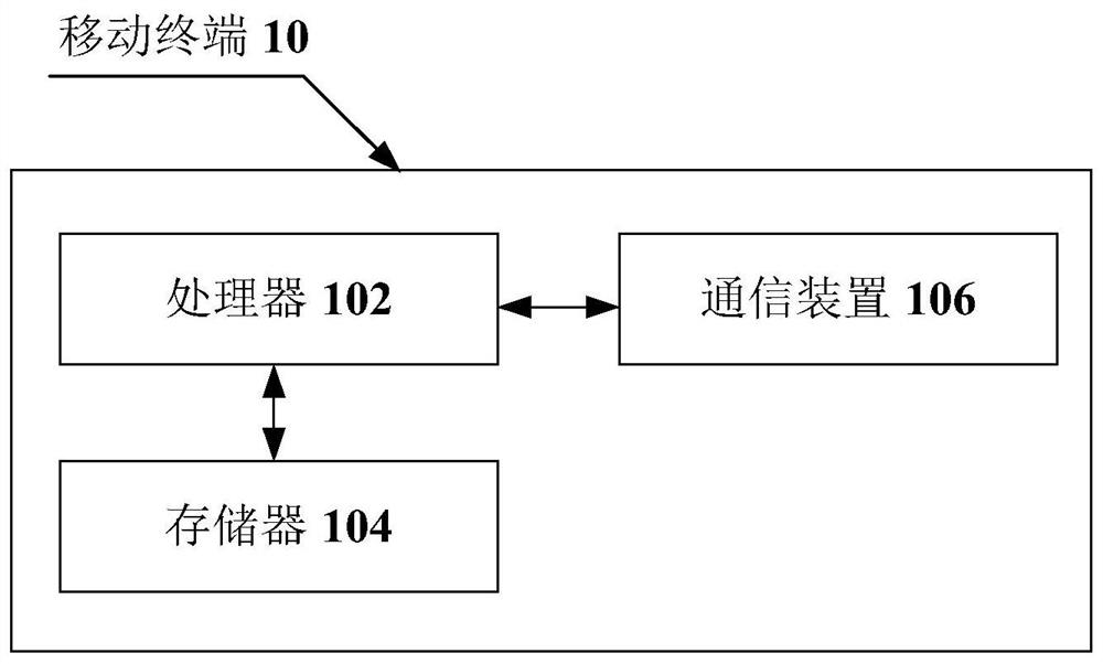
[0064] The method embodiment provided in Embodiment 1 of the present application may be executed in a mobile terminal, a computer terminal, or a similar computing device. Taking running on a mobile terminal as an example, figure 1 It is a hardware structural block diagram of a mobile terminal according to a method for indicating reference signal information in an embodiment of the present invention. Such as figure 1 As shown, the mobile terminal 10 may include one or more (only one is shown in the figure) processor 102 (the processor 102 may include but not limited to a processing device such as a microprocessor MCU or a programmable logic device FPGA, etc.), for A memory 104 for storing data, and a communication device 106 for a communication function. Those of ordinary skill in the art can understand that, figure 1 The shown structure is only for illustration, and it does not limit the structure of the above-mentioned electronic device. For example, the mobile terminal 1...
Embodiment 1
[0106] Preferred embodiment 1: DMRS type 2
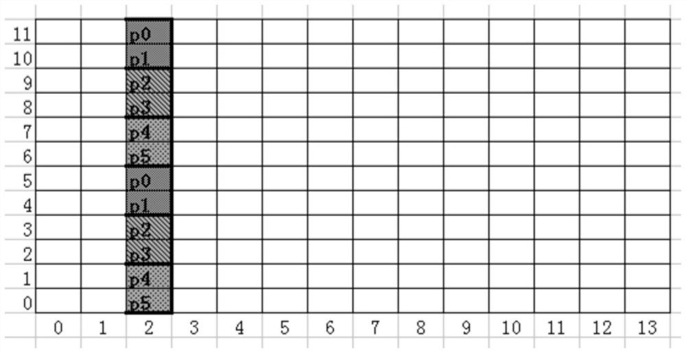
[0107] For the current design of reference signals, a DMRS pattern based on FD-OCC (Frequency domain orthogonal covering code), we call it DMRS type 2, which can effectively support a maximum of 6 ports in one DMRS symbol (such as image 3 shown), supports a maximum of 12 ports in 2 DMRS symbols (such as Figure 4 shown).
[0108] image 3 is a schematic illustration of demodulation reference signal type 2 according to preferred embodiment 1 Figure 1 ,Such as image 3 As shown, in a resource block RB (Resource block), the abscissa is the time domain, and the ordinate is the frequency domain. The 6 DMRS ports are divided into 3 CDM (code domain multiplexing) groups, and the CDM group #0 includes ports p0 and p1. In CDM group #0, ports p0 and p1 are mapped on the same time-frequency resource by means of OCC code division. For example, the OCC code used by port p0 is [1 1], and the OCC code used by port p1 is [1-1]. In one RB, s...
Embodiment 1a
[0200] Preferred Embodiment 1a: DMRS Type 1
[0201] A DMRS pattern based on IFDM (Interleaved Frequency domain multiplexing), which we call DMRS type 1, can effectively support a maximum of 4 ports in one DMRS symbol (such as Image 6 shown), supports a maximum of 8 ports in 2 DMRS symbols (such as Figure 7 shown).
[0202] Image 6 is an illustration of demodulation reference signal type 1 according to the preferred embodiment 1a Figure 1 ,Such as Image 6 As shown, the DMRS port is divided into two CDM groups, CDM group #0 includes p0, p2, and p0, p2 occupy the same time-frequency resources, and are distinguished by different codes, such as different CS (cyclic shift) sequences distinguish. CDM group #1 includes p1 and p3, and p1 and p3 occupy the same time-frequency resource and are distinguished by different codes.
[0203] Figure 7 is an illustration of demodulation reference signal type 1 according to the preferred embodiment 1a Figure II ,exist Figure 7 Amo...
PUM
 Abstract
Description
Claims
Application Information