
Seal structure

A sealing structure and cover technology, which is applied in cooling/heating devices of lighting devices, lighting and heating equipment, semiconductor devices of light-emitting elements, etc., and can solve the problems of cumbersome and complicated installation and wiring operations of wires and sealing sleeves

Inactive Publication Date: 2018-06-05
宣智东
View PDF0 Cites 0 Cited by
  • Summary
  • Abstract
  • Description
  • Claims
  • Application Information

AI Technical Summary

Problems solved by technology

[0003] Usually, in order to improve the sealing performance of the street lamp, it is necessary to set a sealing structure at the connection position where the external wire is inserted into the street lamp. Generally, a through hole for the power supply wire to pass is opened on the housing of the street lamp, and the wire passes through the hole. After passing through the hole, set a sealing sleeve on the inside and outside of the housing respectively, and tighten the two sealing sleeves on the housing, that is, the wires pass through the first sealing sleeve, the housing and the other sealing sleeve in sequence, however , when the wire needs to be installed or replaced, the installation operation of the shell, wire and sealing sleeve in the sealed structure is more cumbersome and complicated, that is, the wiring operation is more cumbersome and complicated

Method used


Image

  • Seal structure
  • Seal structure
  • Seal structure

Examples


Embodiment Construction

[0021] In order to facilitate the understanding of the present invention, the present invention will be described more fully below with reference to the associated drawings. Preferred embodiments of the invention are shown in the accompanying drawings. However, the present invention can be embodied in many different forms and is not limited to the embodiments described herein. On the contrary, the purpose of providing these embodiments is to make the disclosure of the present invention more thorough and comprehensive.

[0022] It should be noted that when an element is referred to as being “fixed” to another element, it can be directly on the other element or there can also be an intervening element. When an element is referred to as being "connected to" another element, it can be directly connected to the other element or intervening elements may also be present. The terms "vertical," "horizontal," "left," "right," and similar expressions are used herein for purposes of ill...


PUM


Abstract

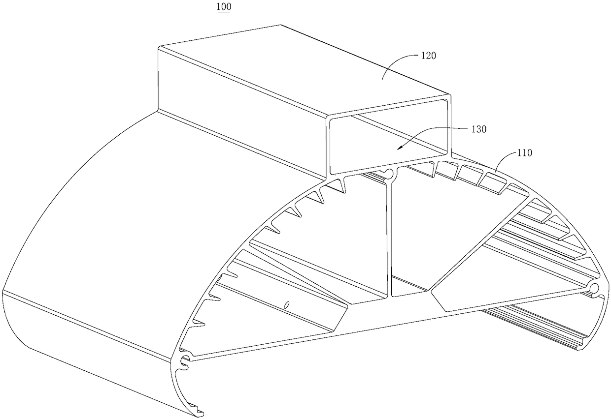
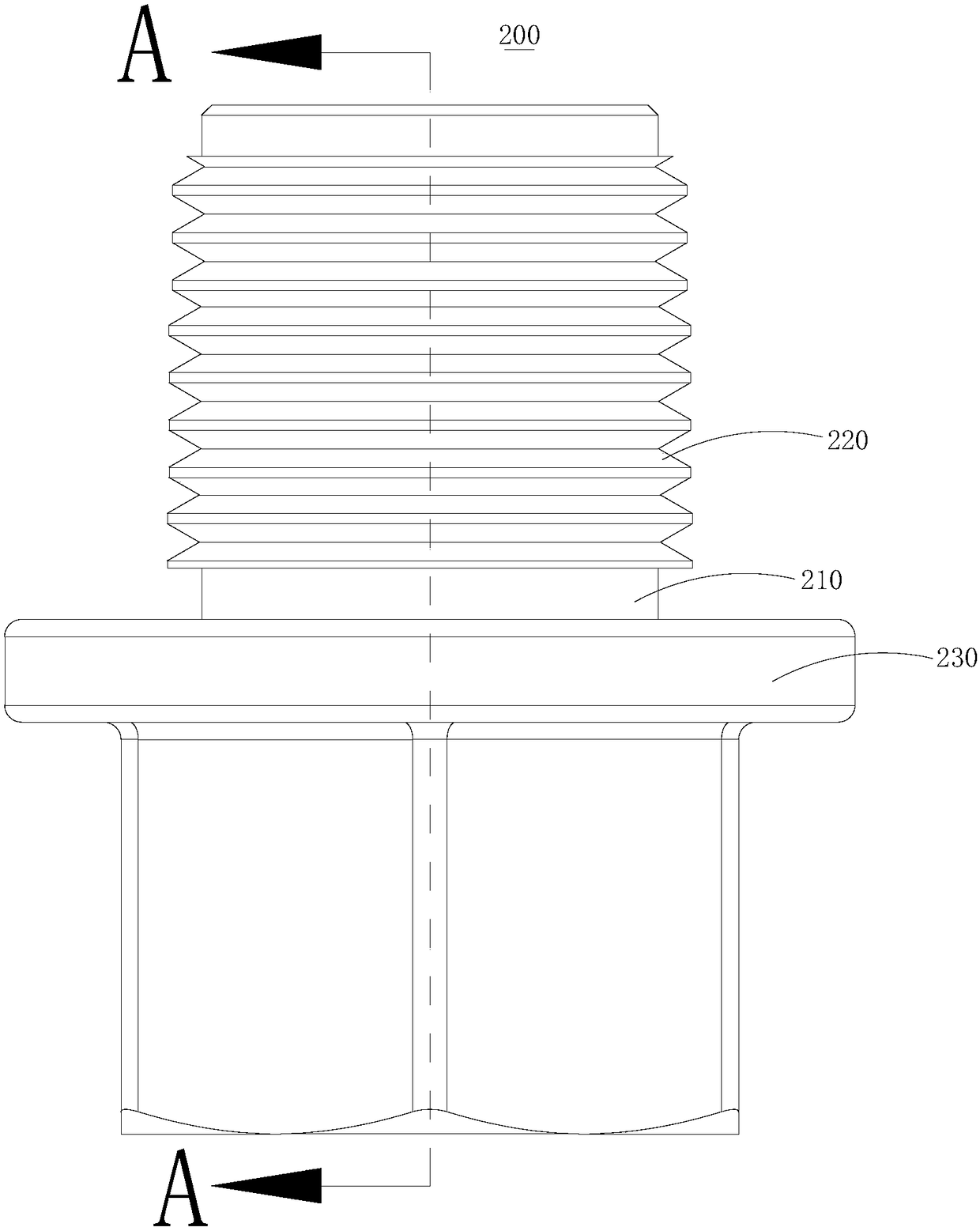
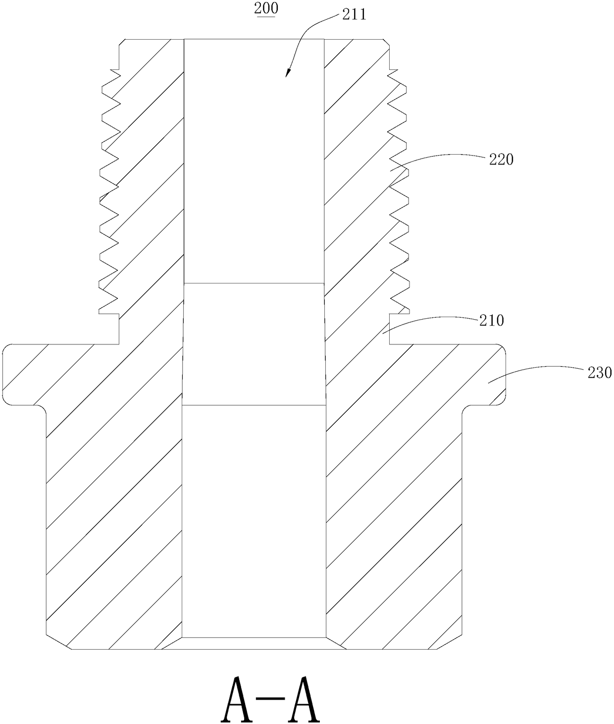
A seal structure comprises a heat dissipation component and a wire connection component. The heat dissipation component comprises a heat radiator and a mounting cover, the mounting cover is fixed to the heat radiator, the mounting cover and the heat radiator jointly form a power source mounting cavity, and the mounting cover is provided with a screw joint hole communicated with the power source mounting cavity. The wire connection component comprises a wire connection sleeve, a screw joint portion and a seal retaining portion. The screw joint portion and the seal retaining portion externally sleeve the wire connection sleeve, the screw joint portion is in screw joint with the screw joint hole, the seal retaining portion is abutted against the outer side wall of the mounting cover, the wireconnection sleeve is provided with a wire connection hole communicated with the power source mounting cavity, and the hole diameter of one end of the wire connection hole is larger than that of the other end of the wire connection hole. Therefore, a whole interference wire connection operation can be completed simply, conveniently and quickly.

Description

technical field [0001] The invention relates to the technical field of heat dissipation, in particular to a sealing structure. Background technique [0002] At present, street lights refer to lamps that provide lighting functions for roads, and generally refer to lamps within the range of road lighting in traffic lighting. Street lamps are widely used in various places where lighting is required. [0003] Usually, in order to improve the sealing performance of the street lamp, it is necessary to set a sealing structure at the connection position where the external wire is inserted into the street lamp. Generally, a through hole for the power supply wire to pass is opened on the housing of the street lamp, and the wire passes through the hole. After passing through the hole, set a sealing sleeve on the inside and outside of the housing respectively, and tighten the two sealing sleeves on the housing, that is, the wires pass through the first sealing sleeve, the housing and t...

Claims


Application Information

Patent Timeline
IPC IPC(8): F21V31/00F21V17/12F21V29/70F21V23/06F21Y115/10
CPCF21V31/005F21V17/12F21V23/06F21V29/70F21Y2115/10
Inventor 宣智东
Owner 宣智东
Learn More