
Self splicing combined plate type film capacitor

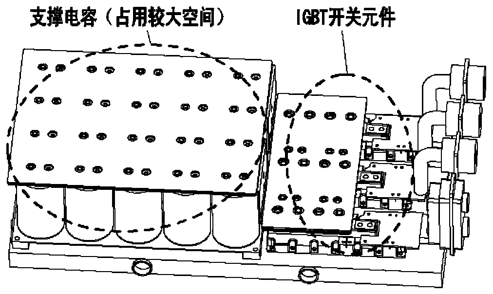
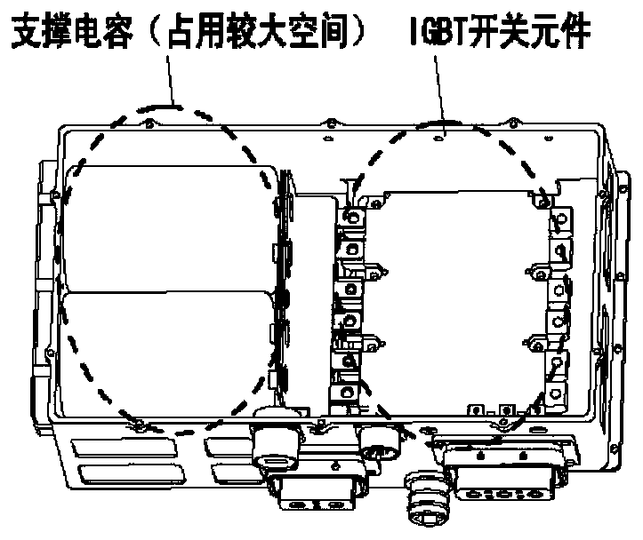
A thin-film capacitor and combined technology, which is applied in the field of capacitors, can solve the problems of large space occupation of supporting capacitors and the reduction of power density of motor controllers, etc., and achieve the effect of reducing the space occupied by vehicle layout and improving power density

Active Publication Date: 2019-09-10
CHINA NORTH VEHICLE RES INST
View PDF6 Cites 0 Cited by
  • Summary
  • Abstract
  • Description
  • Claims
  • Application Information

AI Technical Summary

Problems solved by technology

[0004] The purpose of the present invention is to provide a self-splicing combined plate-type film capacitor, which is used to solve the technical defects of the current supporting capacitor space and volume, and the power density of the motor controller is reduced.

Method used


Image

  • Self splicing combined plate type film capacitor
  • Self splicing combined plate type film capacitor
  • Self splicing combined plate type film capacitor

Examples


Embodiment Construction

[0029] In order to make the purpose, content, and advantages of the present invention clearer, the specific implementation manners of the present invention will be further described in detail below in conjunction with the accompanying drawings and embodiments.

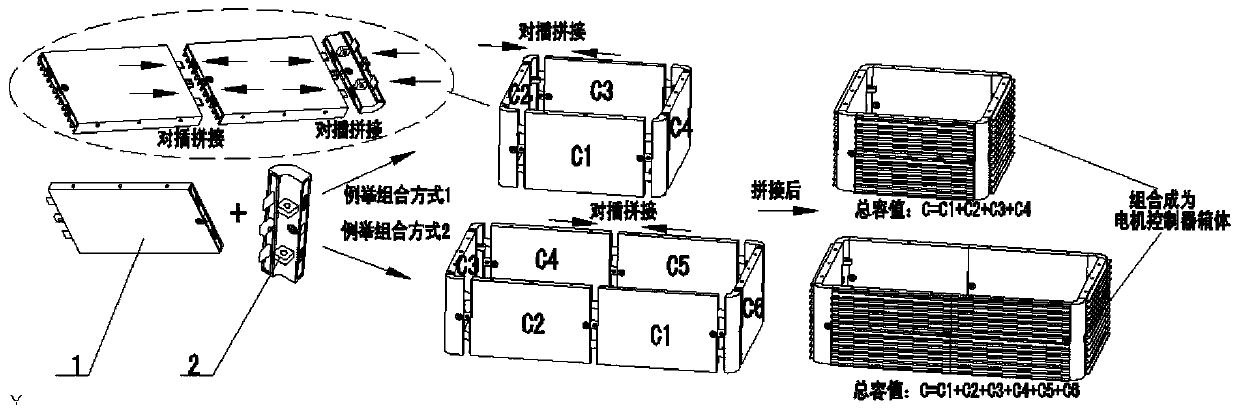
[0030] figure 2 Shown is the splicing structure diagram of the self-splicing combined plate-type film capacitor of the present invention mainly composed of plate-type capacitor substrates, Figure 3a A schematic diagram of a capacitor substrate of the plate type is shown, Figure 3b Shown is a schematic diagram of the capacitor corner connection plate, as figure 2 And as shown in FIG. 3 , a self-splicing combined plate-type film capacitor of the present invention is mainly composed of a plate-type capacitor substrate 1 and a capacitor corner connecting plate 2 spliced ​​together. The plate-type capacitor substrate 1 can be spliced ​​with each other, or can be directly spliced ​​with the capacitor corner connecting ...


PUM


Abstract

The invention discloses a self-spliced combined plate-shaped film capacitor which comprises a plurality of plate-shaped capacitor substrates and a plurality of capacitor corner connecting boards. After two sides of each of the plurality of plate-shaped capacitor substrates are spliced with two sides of the capacitor corner connecting board, an annular member is formed. Two sides of the plate-shaped capacitor substrate are provided with substrate butt-joint fixing-and-fastening interfaces which can be plugged with each other, and locking is performed after the substrate butt-joint fixing-and-fastening interfaces are plugged in place. Two sides of the capacitor corner connecting board are provided with interfaces for connecting with the substrate butt-joint fixing-and-fastening interfaces ofthe plate-shaped capacitor substrate and realizing locking. The capacitor is also provided with an electrode interface. The self-spliced combined plate-shaped film capacitor improves power density ofa motor controller and furthermore reduces occupation space in vehicle arrangement.

Description

technical field [0001] The invention relates to capacitor technology, in particular to a self-splicing combined plate type film capacitor. Background technique [0002] Figure 1a and Figure 1b Shown is a schematic diagram of the main power circuit structure of the existing motor controller, such as Figure 1a as well as Figure 1b As shown, with the development of permanent magnet motor and control technology, there are more and more vehicle applications using permanent magnet motor drive mode (hybrid or pure electric output). The permanent magnet motor drive mode is mainly controlled by the motor controller to drive the permanent magnet motor for drive output. The permanent magnet motor controller is mainly composed of a DSP control circuit and a power circuit. It sends control signals to the IGBT and other power switching elements of the main power circuit through the DSP control circuit board to realize the drive control of the permanent magnet motor. The main power ...

Claims


Application Information

Patent Timeline
Patent Type & Authority Patents(China)
IPC IPC(8): H01G4/224H01G4/33
Inventor 邢彦斌田德文王光辉高香香刘华源韩志平张健姜茹马亚青高晓宇
Owner CHINA NORTH VEHICLE RES INST
Learn More