Wall scraping and stirring device for loading head

A technology of scraping wall mixing and aggregator, which is applied in mixers with rotary mixing devices, mixer accessories, transportation and packaging, etc., can solve the problems of low efficiency, increase motor power, damage, etc., and achieve heat exchange. Uniform and fast, easy disassembly and cleaning, improve work efficiency

Pending Publication Date: 2018-06-08
ZHENGZHOU LION TIGER ABRASIVE MATERIALS & ABRASIVE TOOLS CO LTD
View PDF6 Cites 1 Cited by
  • Summary
  • Abstract
  • Description
  • Claims
  • Application Information

AI Technical Summary

Problems solved by technology

[0003] The scraper of the commonly used wall scraping and stirring device for aggregates is a whole, so the stress is very large during work, which not only increases the power of the motor, but also seriously affects the service life of the machine; the outer surface of the scraping and stirring device for aggregates The frame stirrer is not equipped with a bracket, which is easy to cause deformation and damage to the components during work; the stirrers on the wall scraping stirring device for the aggregate are all rotating in the same direction, although they can stir evenly, but the efficiency is not very high; The rotating shaft of the wall-scraping agitator for the feeder cannot move up and down in a small range, so in some special cases, it is necessary to disassemble the machine, which is time-consuming and labor-intensive; there is no corresponding Mechanism, resulting in uneven stirring, uniform heat transfer, there is no corresponding discharge port on the wall scraping stirring device for the aggregate, so the operation is more complicated. Therefore, in view of the above problems, a scraping stirring device for the aggregate is proposed

Method used


Image

  • Wall scraping and stirring device for loading head
  • Wall scraping and stirring device for loading head

Examples


Embodiment Construction

[0014] The following will clearly and completely describe the technical solutions in the embodiments of the present invention with reference to the accompanying drawings in the embodiments of the present invention. Obviously, the described embodiments are only some, not all, embodiments of the present invention. Based on the embodiments of the present invention, all other embodiments obtained by persons of ordinary skill in the art without making creative efforts belong to the protection scope of the present invention.

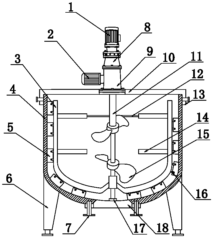
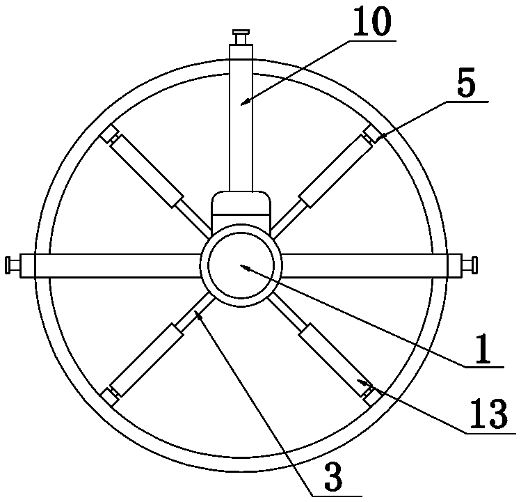
[0015] see Figure 1-2 As shown, a wall scraping and stirring device for a collector includes a housing 4 and a leg 6 arranged at the bottom end of the housing 4. It is characterized in that: the top of the housing 4 is provided with a first bracket 10, and the second A bracket 10 and the housing 4 are connected through a connector 13; the top of the first bracket 10 is provided with a first motor 1, a reducer 8, and a converter 9 in sequence, and a second mot...


PUM


Abstract

The invention discloses a wall scraping and stirring device for a loading head. The wall scraping and stirring device comprises a first motor, a second motor, an outer frame stirrer, a casing, scrapers, support legs, retaining nuts, a speed reducer, a converter, a firs support, a rotating shaft, a second support, connectors, break-angle baffle plates, inner layer stirrers, positioning blocks, a positioning ring and a spherical valve. The break-angle baffle plates are arranged on the outer frame stirrer of the wall scraping and stirring device for the loading head, so that heat exchange of rawmaterials can be more uniform and faster; a rotating shaft of the wall scraping and stirring device for the loading head can realize bi-directional rotation, therefore, not only can stirring be more uniform, but also the work efficiency of the device can be higher; the scrapers of the wall scraping and stirring device for the loading head are mounted in a staggered manner, the casing can be subjected to wall scraping treatment to the maximum extent, and the work efficiency is improved; the positioning ring is arranged at the bottom end of the wall scraping and stirring device for the loading head, accordingly, jittering of the rotating shaft can be controlled effectively, noise is reduced, and safety of the device is improved.

Description

technical field [0001] The invention relates to a wall-scraping stirring device, in particular to a wall-scraping stirring device for a collector, which belongs to the technical field of industry. Background technique [0002] With the continuous development of science and technology, machines from all walks of life are undergoing continuous development and innovation. For example, the mechanism of the scraping and stirring device for the aggregate has undergone great changes. The scraping and stirring is mainly composed of a motor and a stirring mechanism. Among them, the stirring mechanism is the most important. The stirring mechanism is composed of a stirrer, a rotating shaft and a scraper. When working, not only can the stirrer be used to fully and evenly stir the raw materials, but also the scraper can be used to clean the material adhered to the shell. It has a strong working ability to remove the raw materials on it, so the wall scraping and stirring device for the ag...

Claims


Application Information

Patent Timeline
Patent Type & Authority Applications(China)
IPC IPC(8): B01F7/16B01F15/00
CPCB01F27/092B01F27/192B01F27/80B01F35/123
Inventor 邓彬邓全一杨振伟王龙柱
Owner ZHENGZHOU LION TIGER ABRASIVE MATERIALS & ABRASIVE TOOLS CO LTD
Why Eureka
Try Eureka