
Sensor

A sensor and strain gauge technology, applied in the sensor field, can solve the problem that the sensor cannot measure the braking force and gravity of the motor vehicle at the same time

Pending Publication Date: 2018-06-08
BEIJING PANTIAN NEW TECH
View PDF0 Cites 0 Cited by
  • Summary
  • Abstract
  • Description
  • Claims
  • Application Information

AI Technical Summary

Problems solved by technology

[0005] Therefore, the technical problem to be solved by the present invention is to overcome the defect that sensors in the prior art cannot simultaneously measure the braking force and gravity of the motor vehicle

Method used


Image

  • Sensor
  • Sensor
  • Sensor

Examples


Embodiment

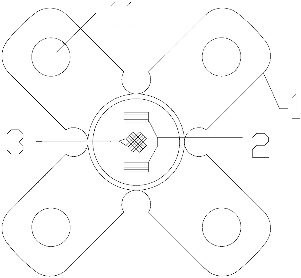
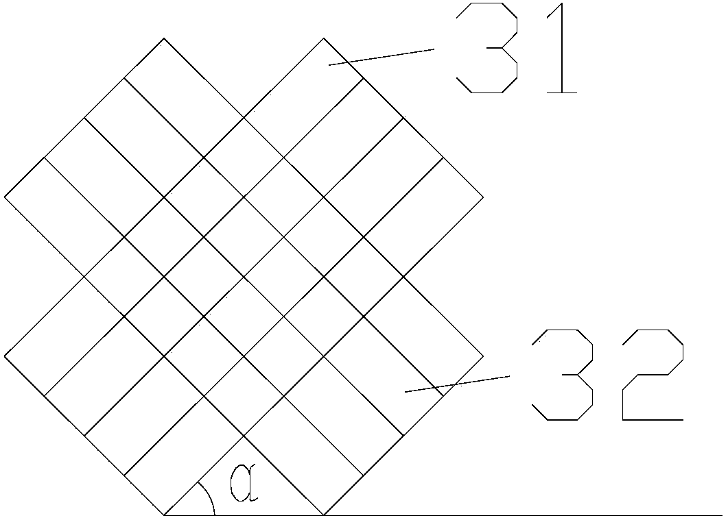
[0029] This embodiment provides a sensor, such as figure 2 As shown, it includes: two stress-sensing teeth 1 vertically connected to each other, and the overlapping parts of the two stress-sensing teeth are provided with strain gauges that elongate or contract synchronously with the stress-sensing teeth, and the strain gauges include: There are two horizontal force strain gauges 2 extending along the horizontal direction; two vertical force strain gauges 3 perpendicular to each other are arranged between the two horizontal force strain gauges.

[0030] The sensor provided in this embodiment is mainly used on the horizontal force beam. The horizontal force beam is set on the ground. The vehicle's own load.

[0031] In this embodiment, the side of the stress-sensing tooth away from the strain gauge is provided with a stress-sensing slot.

[0032] In this embodiment, the angle between any one of the two vertical force strain gauges and the horizontal line is 45° or 135°. From...


PUM


Abstract

The invention provides a sensor including two stress induction teeth in mutual perpendicular connection. An overlapped part of the two stress induction teeth is provided with a strain gage elongatingor contracting along with the stress induction teeth synchronously. The strain gage includes two horizontal force stress gage extending along the horizontal direction and two vertical force stress gage perpendicular to each other and arranged between the two horizontal force stress gage. Through the horizontal force stress gage and the vertical force stress gage, the magnitudes of the horizontal force (braking force) and the shearing force (load) acting on the sensor can be measured.

Description

technical field [0001] The invention relates to the technical field of sensors, in particular to a sensor for measuring the force (horizontal force) during the braking process of a motor vehicle. Background technique [0002] When a motor vehicle is running, it is often necessary to brake it. The force given by the vehicle brake to the motor vehicle is divided into braking force and sideslip force. The size of the braking force determines the length of the braking time of the motor vehicle. If the braking force is too small, the braking time of the motor vehicle will be too long. At this time, there may be a danger of colliding with other motor vehicles, which seriously affects the normal passage of road vehicles. Simultaneously, because the two or four driving wheels of motor vehicle are locked due to mechanical error, there may be inconsistencies in the braking between the wheels. During the driving process of the motor vehicle, once the lateral sliding force of the motor...

Claims


Application Information

Patent Timeline
Patent Type & Authority Applications(China)
IPC IPC(8): G01L5/22G01L5/28
CPCG01L5/22G01L5/28
Inventor 张英杰祝涛李溯李源
Owner BEIJING PANTIAN NEW TECH
Learn More