Cooling structure for water-cooled engine

A water-cooled engine and structure technology, which is applied to the cooling of the engine, engine components, machines/engines, etc., can solve the problems of unable to cool the exhaust side, unable to eliminate the retention of cooling water in the water jacket on the side of the cylinder block, etc., to improve the cooling effect , to prevent the effect of stagnation

Active Publication Date: 2018-06-08
HONDA MOTOR CO LTD +1
View PDF4 Cites 7 Cited by
  • Summary
  • Abstract
  • Description
  • Claims
  • Application Information

AI Technical Summary

Problems solved by technology

However, the invention described in the above-mentioned Patent Document 1 has a problem in that since the cooling water on the intake side of the water jacket on the cylinder block side flows into the cooling water passage, the cooling water on the exhaust side of the water jacket on the cylinder block side cannot be eliminated. stagnation, unable to effectively cool the exhaust side of the cylinder block, which tends to become high temperature

Method used


Image

  • Cooling structure for water-cooled engine
  • Cooling structure for water-cooled engine
  • Cooling structure for water-cooled engine

Examples


no. 1 Embodiment approach

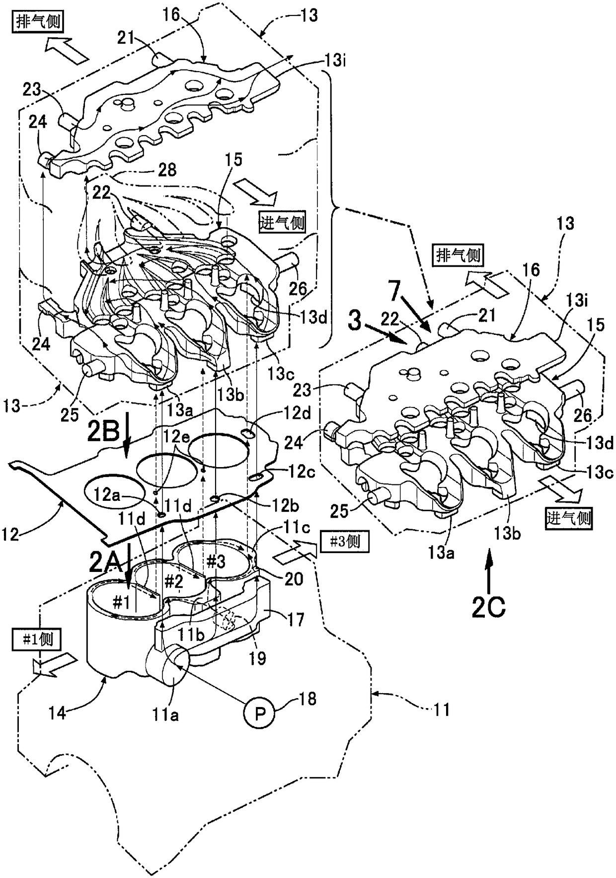
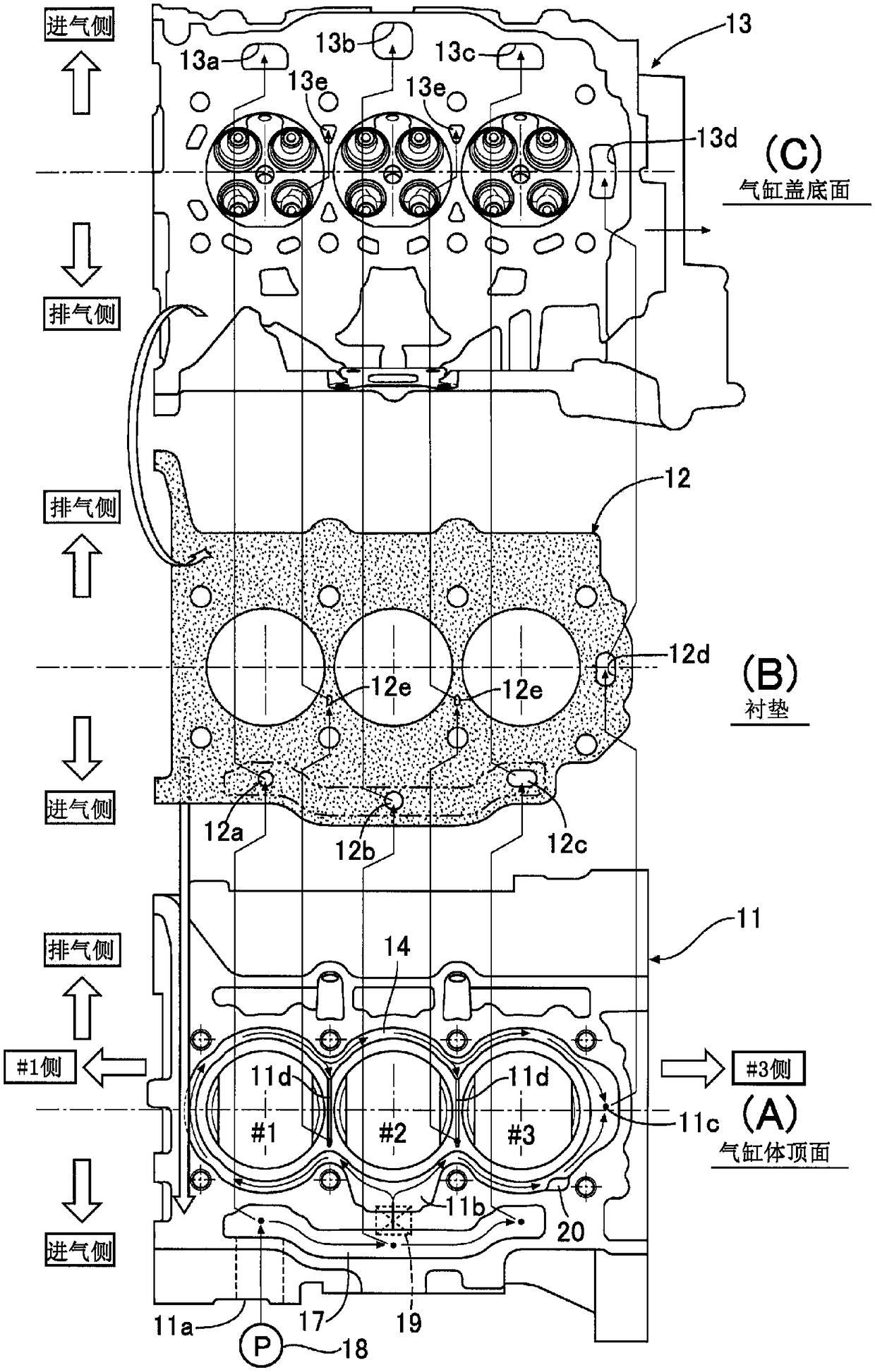
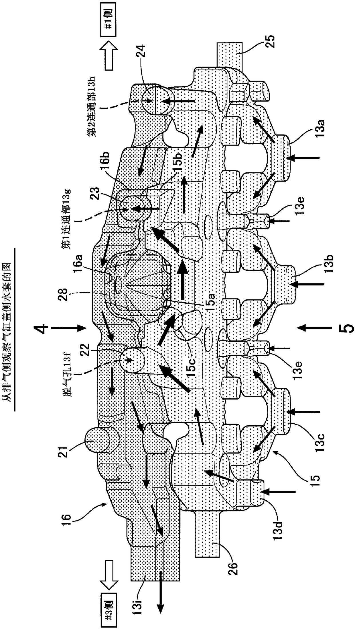
[0064] Such as figure 1 with figure 2 As shown, a water-cooled inline 3-cylinder engine has a cylinder block 11 and a cylinder head 13 whose bottom surface is coupled to the top surface of the cylinder block 11 via a gasket 12. The cylinder block 11 has a cylinder block side water jacket 14 that surrounds the three cylinder bores arranged in line along the cylinder arrangement line. In addition, the cylinder head 13 has a cylinder head that overlaps the exhaust manifold (not shown). Side lower water jacket 15 and cylinder head side upper water jacket 16. in figure 1 The upper left part of the cylinder head 13 shows only the cylinder head side lower water jacket 15 and the cylinder head 13 only shows the cylinder head side upper water jacket 16 respectively. In addition, the shape of the water jacket in each drawing is also the shape of the core of the water jacket formed by casting.

[0065] On the intake side of the cylinder block 11, an auxiliary water jacket 17 extending in ...


PUM


Abstract

According to the present invention, cooling water from a cooling water pump is supplied from a cylinder block-side water jacket formed inside a cylinder block to a cylinder head-side water jacket formed inside a cylinder head, thereby cooling the cylinder block and the cylinder head. At least one cooling water passage that traverses the space between two adjacent cylinder bores is provided, an inlet end of the cooling water passage communicates with an exhaust side of the cylinder block-side water jacket, and an outlet end of the cooling water passage communicates with the cylinder head-side water jacket, and thus by distributing, to the cylinder head-side water jacket via the cooling water passage, the cooling water that flows through the exhaust side of the cylinder block-side water jacket, in addition to a cooling effect between the cylinder bores, the retention of cooling water on the exhaust side of the cylinder block-side water jacket, which reaches high temperatures, can be prevented and the cylinder block cooling effect increased more than if the inlet end of the cooling water passage is made to communicate with an intake side of the cylinder block-side water jacket.

Description

Technical field [0001] The present invention relates to a cooling structure for a water-cooled engine. A cylinder block row composed of a plurality of cylinder barrels and a cylinder block side water jacket surrounding the cylinder block row are formed inside a cylinder block. The body side water jacket supplies cooling water to the cylinder head side water jacket formed inside the cylinder head. Background technique [0002] In the cooling structure of this water-cooled engine, the following structure is known from Patent Document 1 below: a cooling water passage is formed between adjacent cylinder bores, and one end of the cooling water passage is connected to the water jacket on the cylinder block side. The air side is connected, and the other end side as the end of the cooling water passage is connected to the cylinder head side water jacket. By supplying relatively low temperature cooling water on the intake side of the cylinder block side water jacket to the cooling water p...

Claims


Application Information

Patent Timeline
Patent Type & Authority Applications(China)
IPC IPC(8): F02F1/10F01P3/02F02F1/40
CPCF01P3/02F02F1/10F02F1/40
Inventor J·范戈尔文R·拜基希P·拉夫古川和也
Owner HONDA MOTOR CO LTD
Why Eureka
Try Eureka