High Performance Inductors

A technology of inductors and devices, applied in the field of inductors, can solve the problems of limiting inductors, limiting the quality factor of inductors, etc.

Active Publication Date: 2021-06-25
QUALCOMM INC
View PDF14 Cites 0 Cited by
  • Summary
  • Abstract
  • Description
  • Claims
  • Application Information

AI Technical Summary

Problems solved by technology

Such vias are typically cylindrical, square, octagonal, or downwardly tapered trapezoidal in shape, and the effective diameter of the via limits the performance of the inductor by, for example, increasing the resistance of the inductor.
That is, the resistance of the via limits the inductor's quality factor (also known as the Q factor or simply "Q")

Method used


Image

  • High Performance Inductors
  • High Performance Inductors
  • High Performance Inductors

Examples


Embodiment Construction

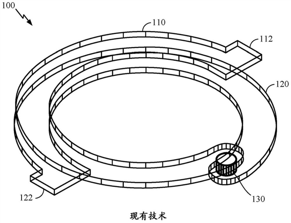
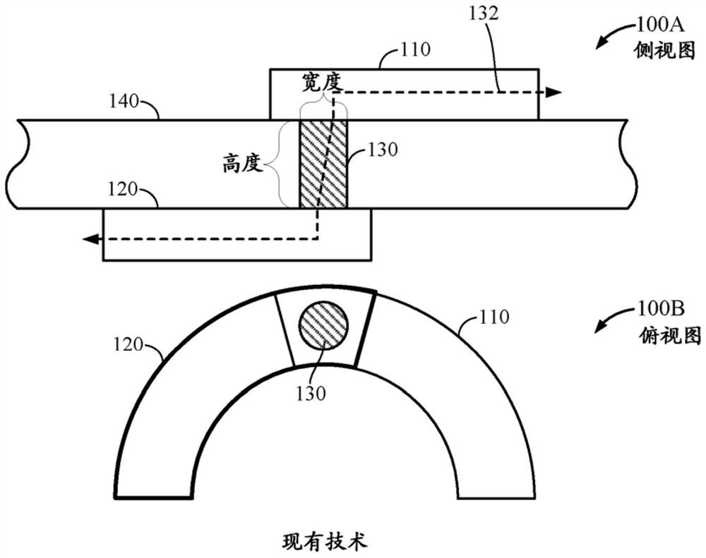
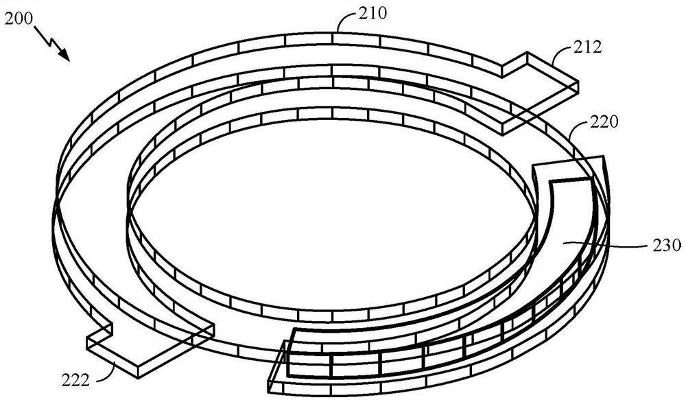
[0022] An inductor device is disclosed that includes a first curved metal plate, a second curved metal plate below the first curved metal plate and substantially vertically aligned with the first curved metal plate, and Vertically aligned first elongated vias between the second curved metal plates, the first elongated vias being configured to conductively couple the first curved metal plate to the second curved metal plate and having a first elongated via of at least about 2 to 1 An aspect ratio of the width to height of an elongated via.

[0023] These and other aspects of the disclosure are disclosed in the following description and associated drawings directed to certain embodiments of the disclosure. Alternative embodiments may be devised without departing from the scope of the present disclosure. Additionally, well-known elements of the disclosure will not be described in detail or will be omitted so as not to obscure the relevant details of the disclosure.

[0024] The...


PUM


Abstract

An inductor device is disclosed that includes a first curved metal plate, a second curved metal plate below the first curved metal plate and substantially vertically aligned with the first curved metal plate, and Vertically aligned first elongated vias between the second curved metal plates, the first elongated vias being configured to conductively couple the first curved metal plate to the second curved metal plate and having a first elongated via of at least about 2 to 1 An aspect ratio of the width to height of an elongated via.

Description

[0001] Cross References to Related Applications [0002] This application claims priority to U.S. Provisional Application No. 62 / 242,720, filed October 16, 2015, entitled "HIGH PERFORMANCE INDUCTORS," which is assigned to the assignee of this application and is expressly incorporated herein by reference in its entirety . technical field [0003] This disclosure relates generally to inductors, and more particularly, but not exclusively, to spiral inductors. Background technique [0004] Inductors are ubiquitous passive analog electronic components used in a variety of power regulation, frequency control and signal conditioning applications in a range of devices including personal computers, tablet computers, wireless mobile handsets and more. [0005] A traditional spiral inductor includes a top metal layer, a bottom metal layer, and vias connecting the top metal layer to the bottom metal layer. The vias allow the induced current to flow from the top metal layer to the bot...

Claims


Application Information

Patent Timeline
Patent Type & Authority Patents(China)
IPC IPC(8): H01F17/00H01F41/04
CPCH01F17/0013H01F41/041H01F2017/002H01F2017/004H01F27/2847H03F15/00H03H7/0138H01F41/04
Inventor D·D·金M·F·维勒兹C·H·芸N·S·穆达卡特金钟海左丞杰D·F·伯迪
Owner QUALCOMM INC
Why Eureka
Try Eureka