Annular steel pipe clamping arm

A technology for clamping arms and steel pipes, applied in the field of mechanical processing, can solve problems such as difficult clamping and difficult to meet the clamping requirements of ring steel pipes

Pending Publication Date: 2018-06-12
TIANJIN ZHI YUAN IND & TRADE
View PDF6 Cites 0 Cited by
  • Summary
  • Abstract
  • Description
  • Claims
  • Application Information

AI Technical Summary

Problems solved by technology

[0002] Due to the excessive arc surface of the ring-shaped steel pipe, it is difficult to clamp during processing, and the existing clamps are difficult to meet the clamping requirements for the ring-shaped steel pipe

Method used


Image

  • Annular steel pipe clamping arm
  • Annular steel pipe clamping arm

Examples


Embodiment Construction

[0019] It should be noted that, in the case of no conflict, the embodiments of the present invention and the features in the embodiments can be combined with each other.

[0020] In describing the present invention, it should be understood that the terms "center", "longitudinal", "transverse", "upper", "lower", "front", "rear", "left", "right", " The orientations or positional relationships indicated by "vertical", "horizontal", "top", "bottom", "inner" and "outer" are based on the orientations or positional relationships shown in the drawings, and are only for the convenience of describing the present invention and Simplified descriptions, rather than indicating or implying that the device or element referred to must have a particular orientation, be constructed and operate in a particular orientation, and thus should not be construed as limiting the invention. In addition, the terms "first", "second", etc. are used for descriptive purposes only, and should not be understood ...


PUM


Abstract

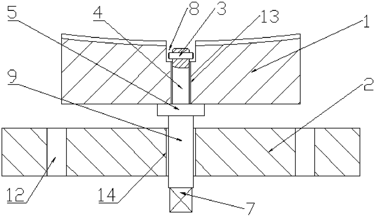
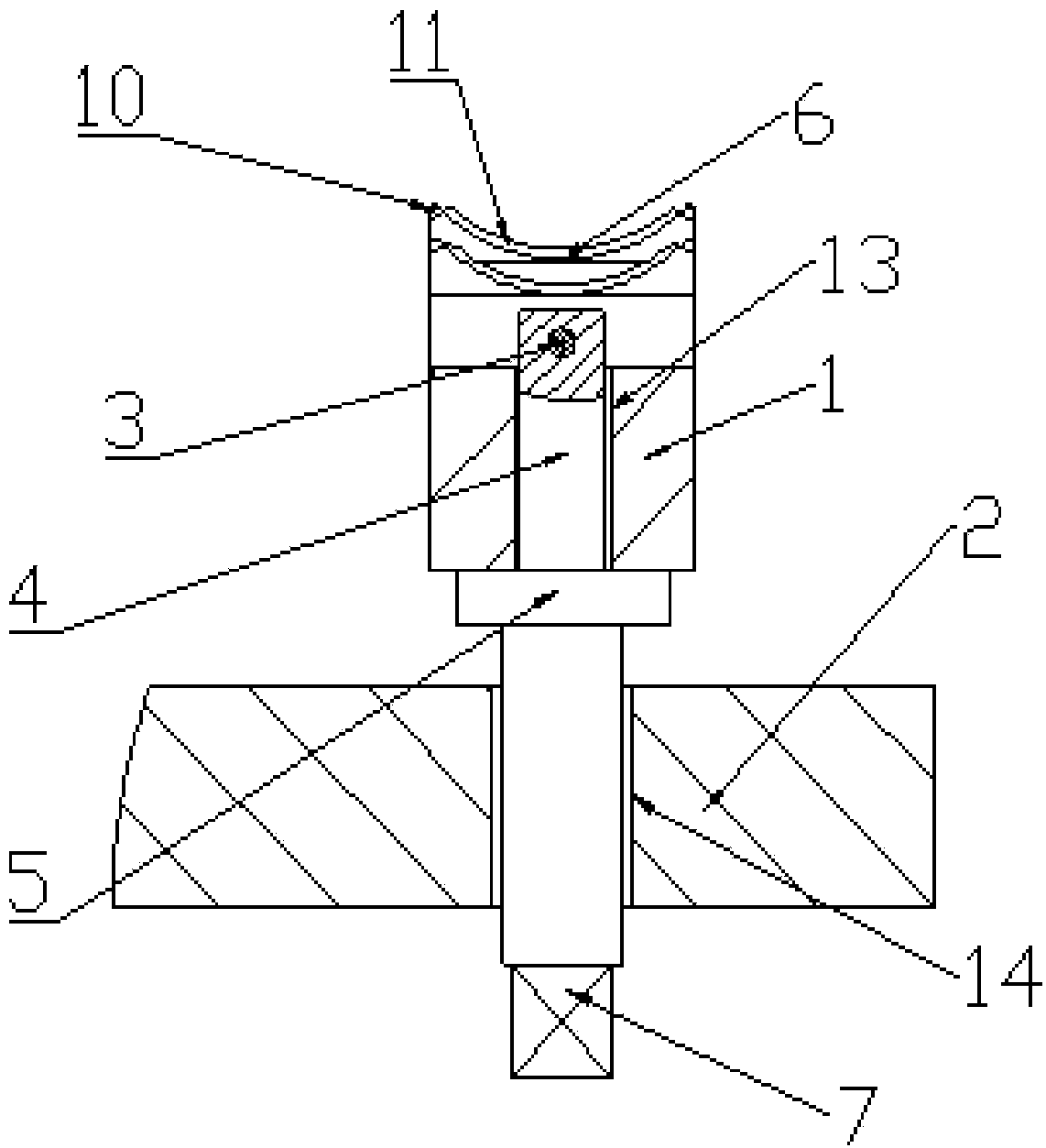
The invention provides an annular steel pipe clamping arm. The side, away from a fixing plate, of a clamping plate is an outer arc face, an arc groove is dug in the outer arc face of the clamping plate, a fixing groove and a limiting hole are dug in the middle of the side, away from the fixing plate, of the clamping plate, the fixing groove is formed in the side, away from the fixing plate, of thelimiting hole, a propelling rod penetrates the fixing plate, a rotation segment and a connecting segment are connected to the two ends of a thread segment, the connecting segment penetrates the limiting hole, and the end, away from the thread segment, of the connecting segment is connected with a limiting pin. According to the annular steel pipe clamping arm, the contact face of a clamp and a workpiece is designed to the corresponding arc face, and meanwhile, the contact face of the clamp and the workpiece is designed to a groove adapting to the tubular workpiece.

Description

technical field [0001] The invention belongs to the field of mechanical processing, and in particular relates to a clamping arm of an annular steel pipe. Background technique [0002] The ring-shaped steel pipe has too many arc surfaces, so it is difficult to clamp during processing, and the existing clamps are difficult to meet the clamping requirements for the ring-shaped steel pipe. Contents of the invention [0003] In view of this, the present invention aims to provide a clamping arm of a ring-shaped steel pipe, which can be well adapted to the clamping of the ring-shaped steel pipe by designing an arc surface equal to that of the clamp. [0004] In order to achieve the above object, technical solution of the present invention is achieved in that way: [0005] A clamping arm of an annular steel pipe, comprising: a body, the body includes a fixing mechanism and a propulsion mechanism. [0006] The fixing mechanism includes a fixing plate and a splint. The fixing plat...

Claims


Application Information

Patent Timeline
Patent Type & Authority Applications(China)
IPC IPC(8): B23Q3/06
CPCB23Q3/06
Inventor 孟繁君庞东生
Owner TIANJIN ZHI YUAN IND & TRADE
Why Eureka
Try Eureka