A kind of temporary reservoir dam

A dam, temporary technology, applied in the field of reservoir appliances, can solve the problem of sandbags scattered and so on

Inactive Publication Date: 2019-06-25
TIANJIN UNIV
View PDF1 Cites 0 Cited by
  • Summary
  • Abstract
  • Description
  • Claims
  • Application Information

AI Technical Summary

Problems solved by technology

[0003] The invention provides a temporary dam of a reservoir. The beneficial effect is that sandbags can be placed in the device, which solves the problem that the sandbags are scattered when the sandbags are directly placed to block water; the slope of the inclined plate of the dam in the device can be adjusted, thereby The inclination of the surface of the dam in contact with the water; the pipe assembly can adjust the inclination of the inclined plate of the dam and the height of the water pipe to control the height of the water surface in the reservoir; multiple devices can be combined to form a long dike
[0004] The invention relates to a reservoir appliance, more specifically a temporary reservoir dam, including a dam body assembly and a pipeline assembly, sandbags can be placed in the device, which solves the problem of sandbags scattered when the sandbags are directly placed to block water; the device The inclination of the inclined plate of the embankment can be adjusted, so as to adjust the inclination of the surface of the embankment in contact with the water; the pipe assembly can not only adjust the inclination of the inclined plate of the embankment, but also adjust the height of the water pipe, so as to realize the control of water in the reservoir The height of the water surface; several units can be combined to form a long embankment

Method used


Image

  • A kind of temporary reservoir dam
  • A kind of temporary reservoir dam
  • A kind of temporary reservoir dam

Examples


specific Embodiment approach 1

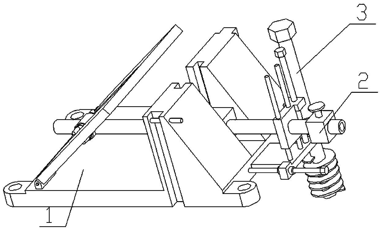
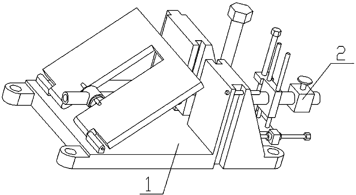
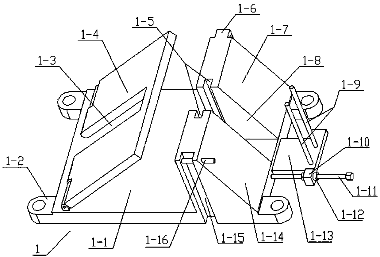
[0021] Combine below Figure 1-6 Describe this embodiment, the present invention relates to a kind of reservoir appliance, more specifically a kind of reservoir temporary embankment, including embankment body assembly 1 and pipeline assembly 2, sandbags can be placed in the device, which solves the problem of water blocking when directly placing sandbags The problem of sandbags scattered during time; the inclination of the inclined plate of the dam in the device can be adjusted, thereby adjusting the inclination of the surface at the end of the dam in contact with water; Height, to control the height of the water surface in the reservoir; multiple devices can be combined to form a long embankment.

[0022] The dam body assembly 1 includes a bottom plate 1-1, a middle groove 1-3 of a dam slant plate, a dam slant plate 1-4, a convex groove 1-5, a trapezoidal seat I1-7, a trapezoidal inter-seat groove 1-8, Vertical round rod 1-9, horizontal adjustment screw seat 1-10, horizontal...


PUM


Abstract

The invention relates to a reservoir tool, in particular to a temporary dam for a reservoir. The temporary dam comprises a dam body assembly and a pipeline assembly. Sand bags can be placed in the temporary dam, and the problem that sand bags are scattered when directly placed for blocking water is solved; the slope of a dam oblique plate of the temporary dam can be adjusted so as to adjust the inclination degree of the surface of the end, making contact with water, of the dam; and the pipeline assembly can adjust the slope of the dam oblique plate and also adjust the height of a water pipe, so that the height of the water level in the reservoir is controlled. The dam oblique plate is hinged to the left end of a bottom plate, a dam oblique plate middle groove is formed in the middle of thedam oblique plate, a trapezoid seat I is welded to the rear end of the right end of the bottom plate, and a trapezoid seat II is welded to the front end of the right end of the bottom plate; and a trapezoid seat space groove is formed between the trapezoid seat I and the trapezoid seat II, the trapezoid seat space groove and the trapezoid seat II are each provided with a ribbed groove, and the two ribbed grooves are oppositely arranged, and a sliding groove corresponding to a sliding plate is formed in the middle of the right end of the bottom plate.

Description

technical field [0001] The invention relates to a reservoir appliance, in particular to a temporary reservoir dam. Background technique [0002] The application number is CN201620240759.1 for a waterproof dam with improved impact resistance. The utility model discloses a waterproof dam with improved impact resistance, which includes a dam body 1. The dam body 1 is provided with a front slope 101 and a rear slope 102, it is characterized in that: the front slope 101 of the dam body 1 is provided with several conical dams 2 in sequence along the bottom line of the slope, the edge at the bottom of the conical dam 2 coincides with the bottom line of the front slope 101, and two adjacent conical dams 2 The vertices of the bottom abut against each other, and the side of the conical dike 2 opposite to the front slope 101 and the front slope 101 are filled with corresponding concrete or earth and rocks. The utility model not only has high cost performance, but also can effectively ...

Claims


Application Information

Patent Timeline
Patent Type & Authority Patents(China)
IPC IPC(8): E02B3/10
CPCE02B3/10E02B3/102E02B3/106E02B3/108
Inventor 卢陈涛练继建
Owner TIANJIN UNIV
Why Eureka
Try Eureka