Improved structure of door lock of electrical cabinet

A technology for electrical cabinets and door locks, which is applied to building locks, building structures, locks controlled by non-mechanical transmission, etc., can solve the problems of no significant improvement in anti-theft performance, inconvenient installation and use, and low reliability, and achieve strong anti-theft performance , Easy operation and high reliability

Pending Publication Date: 2018-06-12
ZHEJIANG ZHONGZHENG LOCK CO LTD
View PDF3 Cites 2 Cited by
  • Summary
  • Abstract
  • Description
  • Claims
  • Application Information

AI Technical Summary

Problems solved by technology

[0003] In order to overcome the problems in the prior art that the electromagnetic control and mechanical control of the ordinary electrical cabinet door lock can only be used alone, the anti-theft performance has not been significantly improved, the structure is too complicated, the reliability is low, and the installation and use are relatively inconvenient. An improved structure of an electric cabinet door lock is provided, the improved structure of the electric cabinet door lock has compact design, convenient operation and use, strong anti-theft performance and high reliability

Method used


Image

  • Improved structure of door lock of electrical cabinet
  • Improved structure of door lock of electrical cabinet
  • Improved structure of door lock of electrical cabinet

Examples


Embodiment Construction

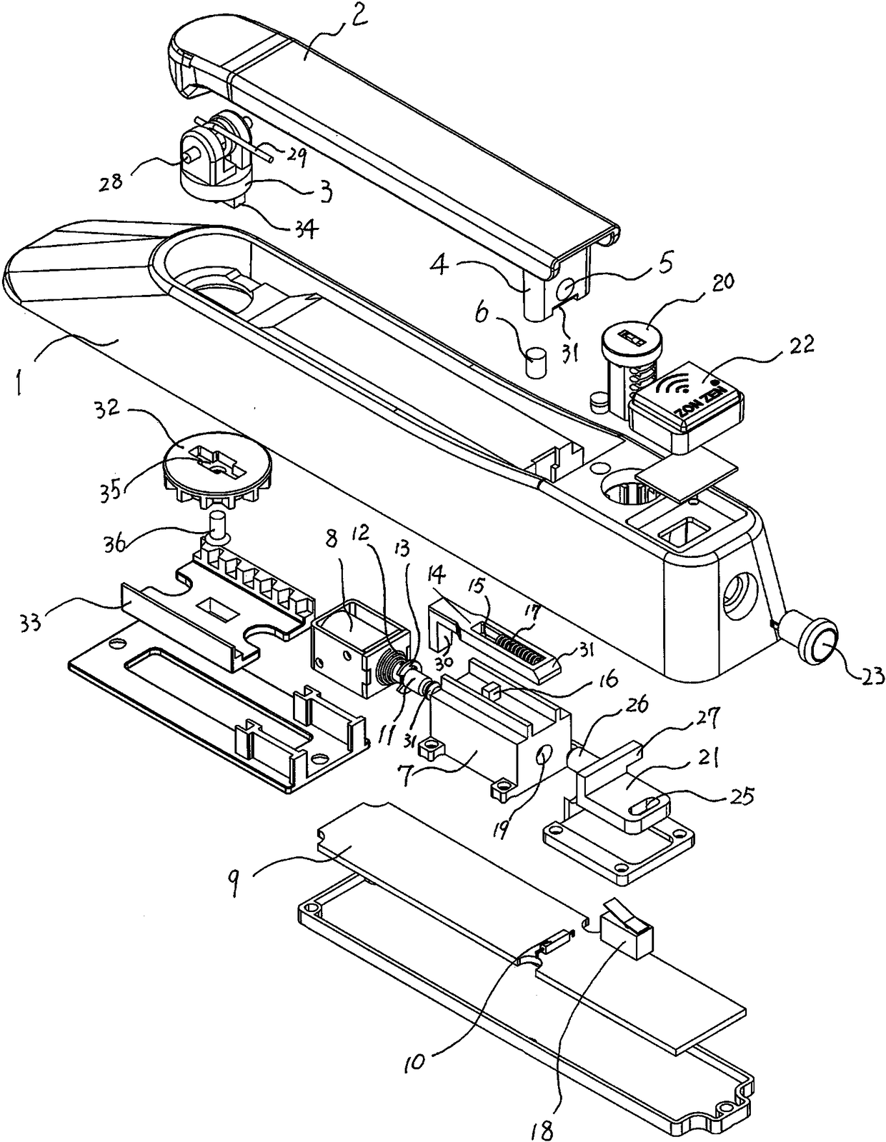
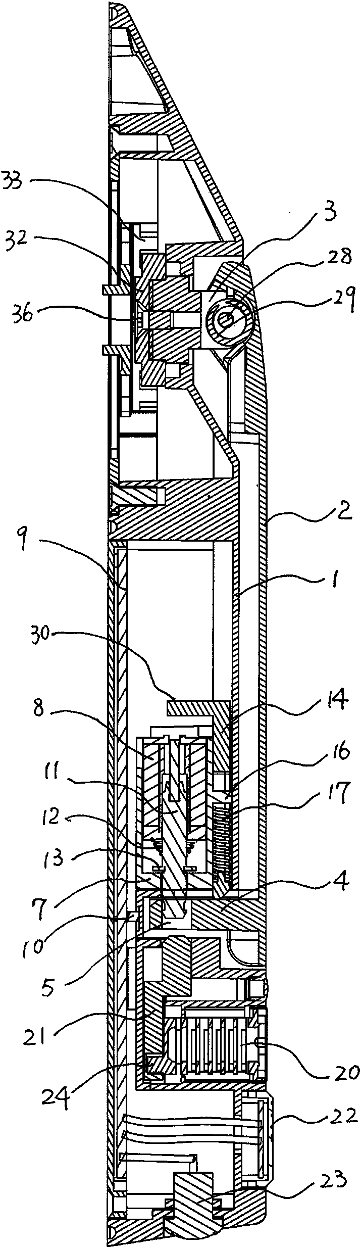
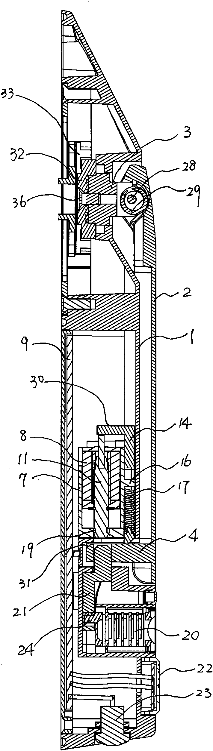
[0016] As shown in the figure, the present invention includes a lock body 1, a handle 2 and a lock shaft 3. The upper end of the handle 2 is hinged to one end of the lock shaft 3 through a pin shaft 28 and a torsion spring 29, and the handle 2 drives the door leaf to lock through the lock shaft 3. There is a protruding locking part 4 at the lower end of the handle 2 toward the lock body 1. The locking part 4 is provided with a locking hole 5 and a magnetic block 6. On the side of the lock body 1 opposite to the locking part 4 Coil support 7 is set, and electromagnetic coil 8 is fixed in coil support 7 and joins with circuit board 9, and circuit board 9 is provided with touch switch 18 and handle inductor 10 that matches with magnetic block 6, can be in the electromagnetic coil 8 Slide lock pin 11 is installed in sliding location, and slide lock pin 11 outerwear first back-moving spring 12, first back-moving spring 12 presses between electromagnetic coil 8 and the radially fixed...


PUM


Abstract

The invention relates to an improved structure of a door lock of an electrical cabinet. The improved structure comprises a lock body, a lever handle and a locking shaft, wherein a coil bracket is arranged in the lock body; a solenoid coil is fixedly arranged in the coil bracket and the solenoid coil is connected with a circuit board; a contact switch and a lever handle inductor are arranged on thecircuit board; a slide lock pin is arranged in the solenoid coil; a first return spring sleeves outside the slide lock pin; the slide lock pin is matched with a locking hole in the lever handle; a return tongue is arranged above the coil bracket; a return slide slot is formed in the return tongue; the return slide slot is in sliding fit to a stop pin fixedly arranged on the top of the coil bracket; the stop pin abuts against a second return spring in the return slide slot; the front end part of the return tongue is matched with the locking part; a lock cylinder, a spring bolt, a card-swipinginductor and a trigger switch are mounted in the lower end part of the lock body; a driving lever for driving the spring bolt to move is arranged on the lock cylinder in an eccentric mode; a pushing rod and a pressure table are further arranged on the spring bolt; and the pushing rod and the pressure table are separately matched with the slide lock pin and the contact switch. The improved structure has the advantages of being compact in structure, convenient to operate and use, strong in burglar resistance and high in reliability.

Description

technical field [0001] The invention relates to an improved structure of an electric cabinet door lock. Background technique [0002] In order to improve the anti-theft performance of locks, locks using electromagnetic and mechanical dual control have appeared in the prior art, but the electromagnetic control and mechanical control of the above-mentioned locks can only be used alone, the anti-theft performance has not been significantly improved, and its structure is too complicated , low reliability, and inconvenient installation and use. Contents of the invention [0003] In order to overcome the problems in the prior art that the electromagnetic control and mechanical control of the ordinary electrical cabinet door lock can only be used alone, the anti-theft performance has not been significantly improved, the structure is too complicated, the reliability is low, and the installation and use are relatively inconvenient. An improved structure of an electric cabinet door...

Claims


Application Information

Patent Timeline
Patent Type & Authority Applications(China)
IPC IPC(8): E05B47/06E05B63/00E05B65/02E05B65/52
CPCE05B47/0657E05B63/0065E05B65/02E05B65/52E05B2047/0086E05B2047/0091E05B2047/0073
Inventor 陈成忠
Owner ZHEJIANG ZHONGZHENG LOCK CO LTD
Why Eureka
Try Eureka