
Generator waste heat utilization adjustment components

A technology for generating waste heat and adjusting components, which is applied to engine components, valve details, mechanical equipment, etc., can solve the problems of waste of flue gas, waste of waste heat, unstable flue gas discharge pressure, etc., to improve economy and comprehensive energy efficiency Effect

Active Publication Date: 2019-07-12
ENN ENERGY SERVICE
View PDF6 Cites 0 Cited by
  • Summary
  • Abstract
  • Description
  • Claims
  • Application Information

AI Technical Summary

Problems solved by technology

[0003] Generally, in order to ensure the stable and efficient power generation of the generator set, the generator set and the waste heat flue gas utilization equipment generally adopt a one-to-one principle. The pressure of the flue gas discharge needs to be kept stable, and when the flue gas enters the waste heat utilization unit, it is affected by the fluctuation of the cooling and heat demand at the end. Changes in the utilization of flue gas waste heat can easily lead to unstable flue gas discharge pressure, so that the generator set needs to meet the demand of end flue gas waste heat for partial load power generation or set up a bypass pipe to discharge excess flue gas to the atmosphere, resulting in waste heat waste
[0004] The existing waste heat utilization considers to ensure the back pressure of the flue gas emitted by the generator set, and gives up the possibility of diversifying the use of flue gas, or directly causes waste of flue gas, so there is room for improvement

Method used


Image

  • Generator waste heat utilization adjustment components
  • Generator waste heat utilization adjustment components
  • Generator waste heat utilization adjustment components

Examples


Embodiment Construction

[0027] Embodiments of the present invention are described in detail below, examples of which are shown in the drawings, wherein the same or similar reference numerals designate the same or similar elements or elements having the same or similar functions throughout. The embodiments described below by referring to the figures are exemplary only for explaining the present invention and should not be construed as limiting the present invention.

[0028] In describing the present invention, it should be understood that the terms "center", "longitudinal", "transverse", "length", "width", "thickness", "upper", "lower", "front", " Back", "Left", "Right", "Vertical", "Horizontal", "Top", "Bottom", "Inner", "Outer", "Axial", "Radial", "Circumferential", etc. The indicated orientation or positional relationship is based on the orientation or positional relationship shown in the drawings, and is only for the convenience of describing the present invention and simplifying the description,...


PUM


Abstract

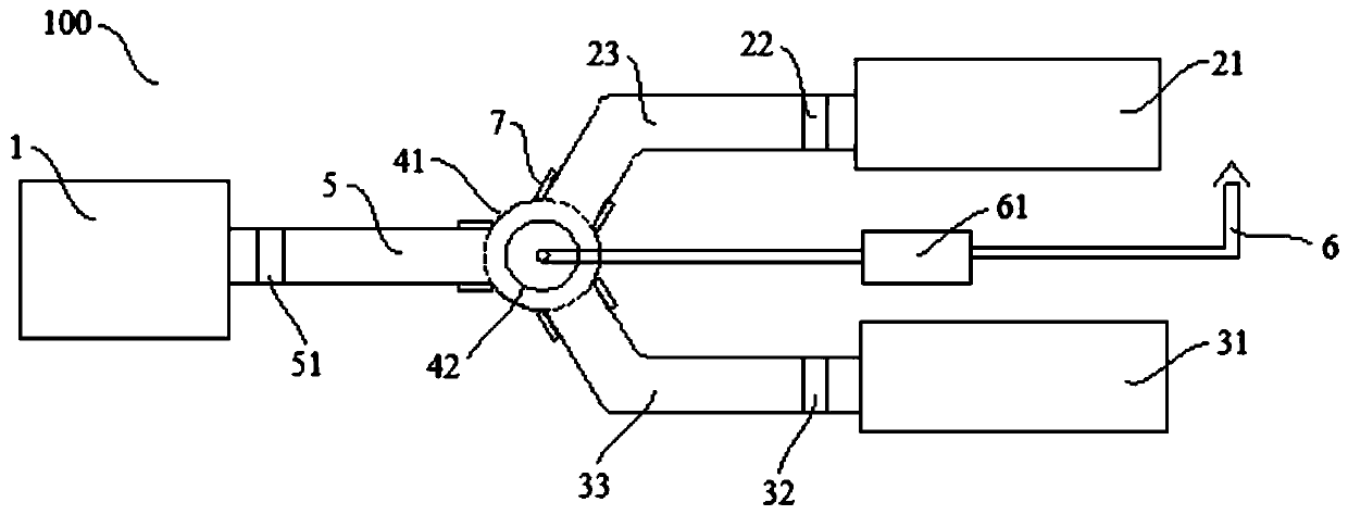
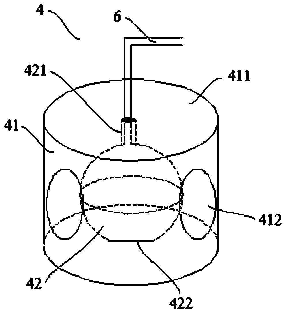
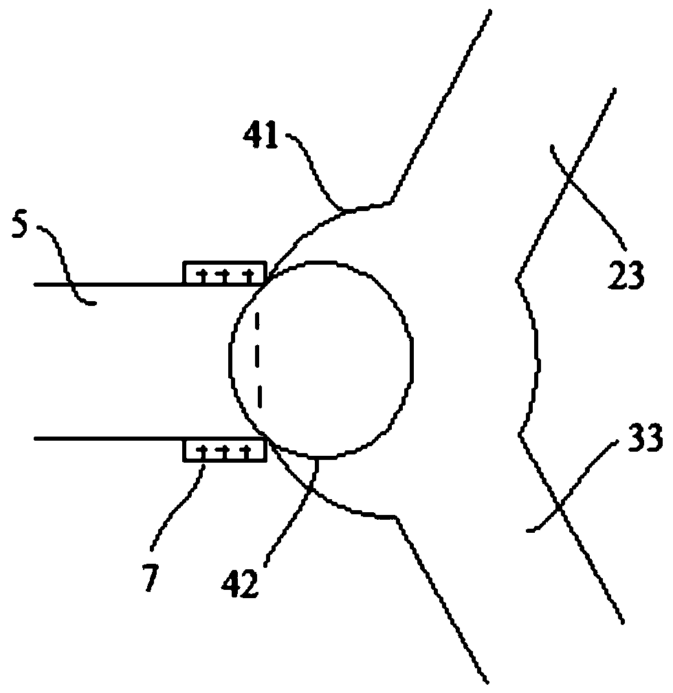
The invention discloses a power generator waste-heat utilization regulating assembly which comprises a power generator, a plurality of groups of waste-heat utilization equipment, a flue gas flow-splitregulating device and a driving device, wherein the power generator is used for generating power and waste gas through combustion; the flue gas flow-split regulating device is arranged between the power generator and the waste-heat utilization equipment so as to change the flow direction and the flow rate of the waste gas, and comprises a shell and a floating ball valve arranged in the shell; a plurality of communicating holes are formed in the peripheral surface of the shell; one communicating hole is connected with the power generator through a gas exhaust pipe so as to receive the waste gas; pressure sensors are arranged on the gas exhaust pipe; other communicating holes are connected with the corresponding waste-heat utilization equipment through gas inlet pipes; and the driving device is used for driving the floating ball valve to move and enclose at most one communicating hole at the same time. According to the power generator waste-heat utilization regulating assembly disclosedby the invention, the number of utilization hours of a power generator set can be increased and the maximum utilization can be achieved through less regulating operation.

Description

technical field [0001] The invention relates to the field of energy, in particular to a generator waste heat utilization adjustment assembly. Background technique [0002] Common generator sets in the field of natural gas distributed energy include gas turbines, internal combustion engines, steam turbines, etc. The flue gas emitted by gas turbines and internal combustion engines has a large amount of waste heat. The waste heat utilization method can be selected according to the demand for hot and cold steam at the end. Lithium bromide unit (to produce cold and hot water), Waste heat boiler (to produce steam), flue gas hot water plate heat exchanger (to produce hot water), etc. [0003] Generally, in order to ensure the stable and efficient power generation of the generator set, the generator set and the waste heat flue gas utilization equipment generally adopt a one-to-one principle. The pressure of the flue gas discharge needs to be kept stable, and when the flue gas enters...

Claims


Application Information

Patent Timeline
Patent Type & Authority Patents(China)
IPC IPC(8): F16K31/18F16K27/02
CPCF16K27/0263F16K31/18
Inventor 高小燕黄宇斌黄袆林王淞
Owner ENN ENERGY SERVICE
Learn More