Spline claw and chaining claw diversion assembly inside valve body

A flower claw and valve body technology, applied in the direction of fluid flow, valve energy absorption device, valve details, etc., can solve the problems that the water flow cannot be separated and the diversion effect is not obvious.

Inactive Publication Date: 2018-06-12
安徽省华象铜业有限公司
View PDF5 Cites 0 Cited by
  • Summary
  • Abstract
  • Description
  • Claims
  • Application Information

AI Technical Summary

Problems solved by technology

[0003] At present, in most valves, the combination of link claws and flower claws with diverting effects is not significant, and it is impossible to separate the water flow carefully.

Method used


Image

  • Spline claw and chaining claw diversion assembly inside valve body
  • Spline claw and chaining claw diversion assembly inside valve body

Examples


Embodiment Construction

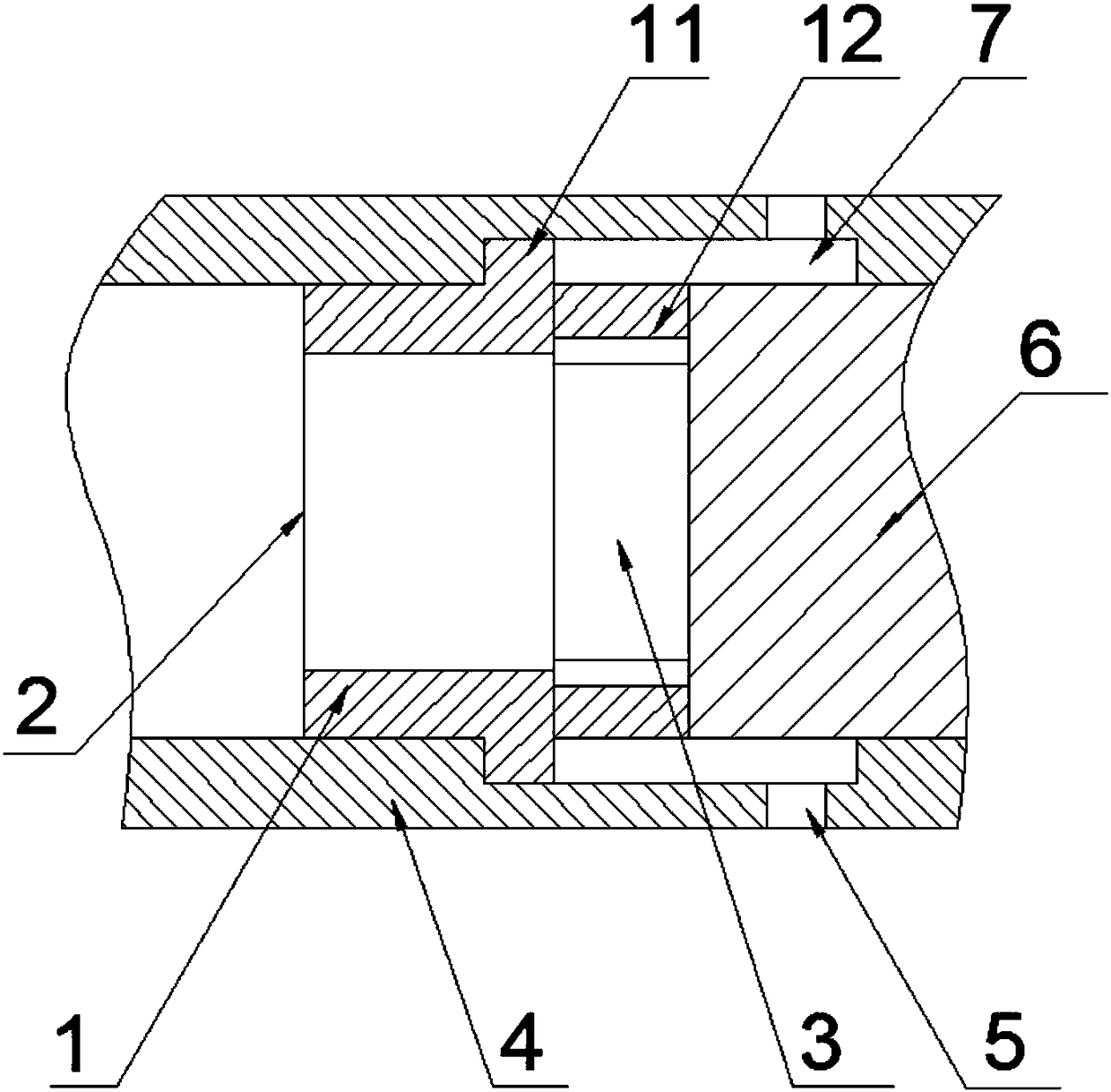
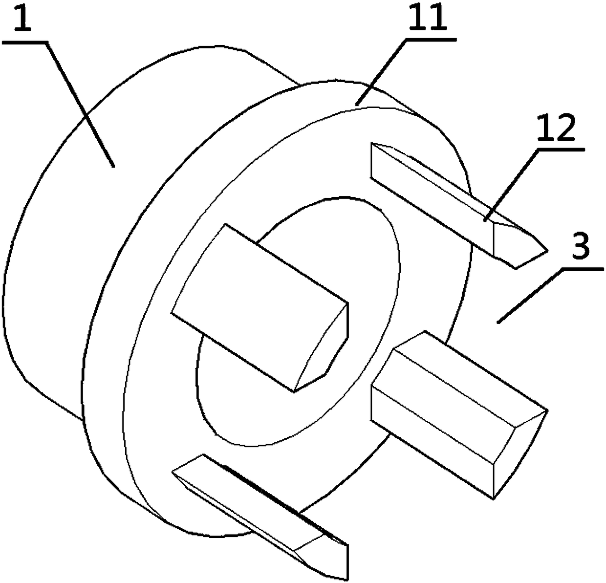
[0012] Such as Figure 1-2 as shown, figure 1 It is a schematic diagram of the overall connection of the flower claw inside the valve body and the link claw shunt assembly proposed by the present invention, figure 2 It is a schematic diagram of the structure of the connecting claw in the spline claw and the connecting claw inside the valve body proposed by the present invention.

[0013] refer to Figure 1-2 , a shunt assembly between the flower claw and the link claw inside the valve body proposed by the present invention, including the link claw 1, the flower claw 4 and the connecting part 6; , the bump 11 and the flower claw 4 are fixed at the limit; the center of the link claw 1 is provided with a through hole in the axial direction, one end of the link claw 1 is the water inlet 2, and the other end of the link claw 1 is symmetrically provided with four shunt claws 12, between the shunt claws 12 A water outlet 3 is formed, and a connecting part 6 is arranged close to t...


PUM


Abstract

The invention discloses a spline claw and chaining claw diversion assembly inside a valve body. The spline claw and chaining claw diversion assembly comprises a chaining claw, a spline claw and a connecting component; the chaining claw is arranged in the spline claw in a matched mode, a convex block is arranged on the periphery of the chaining claw, and the convex block and the spline claw is limited and fixed; a through hole is formed in the center of the chaining claw in the axial direction, one end of the chaining claw is a water inlet end, four diversion claws are symmetrically arranged atthe other end of the chaining claw, and a water outlet end is formed among the diversion claws, and the end parts of the diversion claws are close to the connecting part; the outer sides of the diversion claws, the outer side of the connecting part and the inner side of the spline claw form a water flow channel, and multiple water outlet holes are formed in the spline claw; and the water inlet end of the chaining claw, the water outlet end of the diversion claws, the water flow channel and the water outlet holes form a complete water flow diversion channel. According to the embodiment, the four diversion claws are symmetrically arranged at the end part of the chaining claw, the diversion claws are used for carrying out four-section diversion treatment on water flow, so that diversion of the water flow is more uniform and refined.

Description

technical field [0001] The invention relates to the field of valves, in particular to a flow diverting assembly of spline claws and link claws inside a valve body. Background technique [0002] The valve is a control component in the fluid delivery system, which has functions such as cut-off, adjustment, flow diversion, reverse flow prevention, pressure stabilization, flow diversion or overflow pressure relief. The valves used in the fluid control system range from the simplest cut-off valve to the various valves used in the extremely complex automatic control system. There are quite a variety of varieties and specifications; [0003] At present, in most valves, the combination of link claws and flower claws with diverting effects is not significant, and the water flow cannot be separated carefully. In this embodiment, the structure of the linking claw is modified to make the diversion effect of the water flow more uniform and refined. Contents of the invention [0004] ...

Claims


Application Information

Patent Timeline
IPC IPC(8): F16K47/00F15D1/00
CPCF16K47/00F15D1/00
Inventor 熊孝云
Owner 安徽省华象铜业有限公司
Why Eureka
Try Eureka