Air duct type electronic air purification machine
An electronic air and purifier technology, applied in the direction of dispersed particle separation, chemical instruments and methods, separation methods, etc., can solve the problem of plasma concentration reduction, achieve the effect of TVOC degradation, good reliability, and simple structure
- Summary
- Abstract
- Description
- Claims
- Application Information
AI Technical Summary
Problems solved by technology
Method used
Image
Examples
Embodiment 1
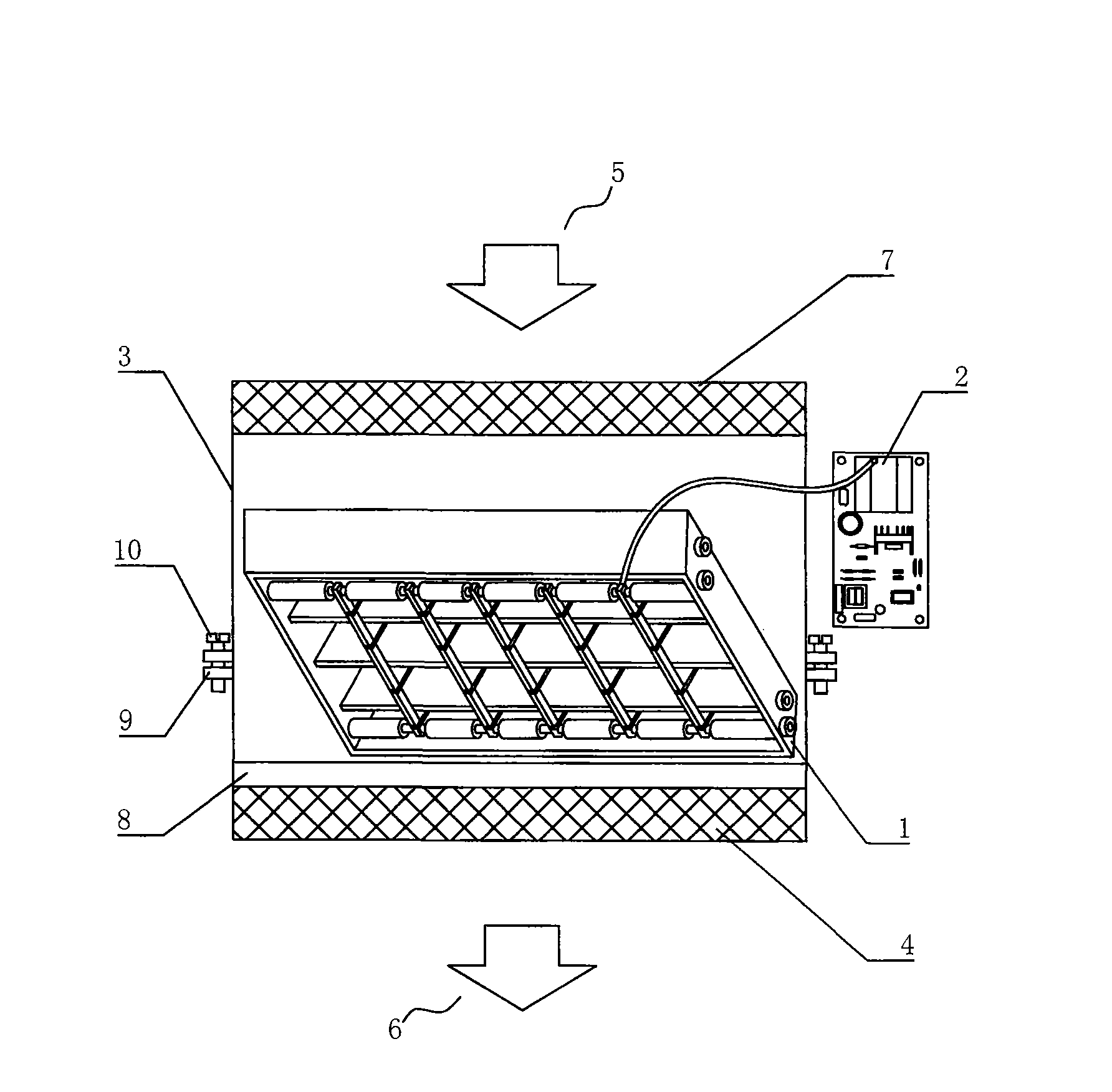
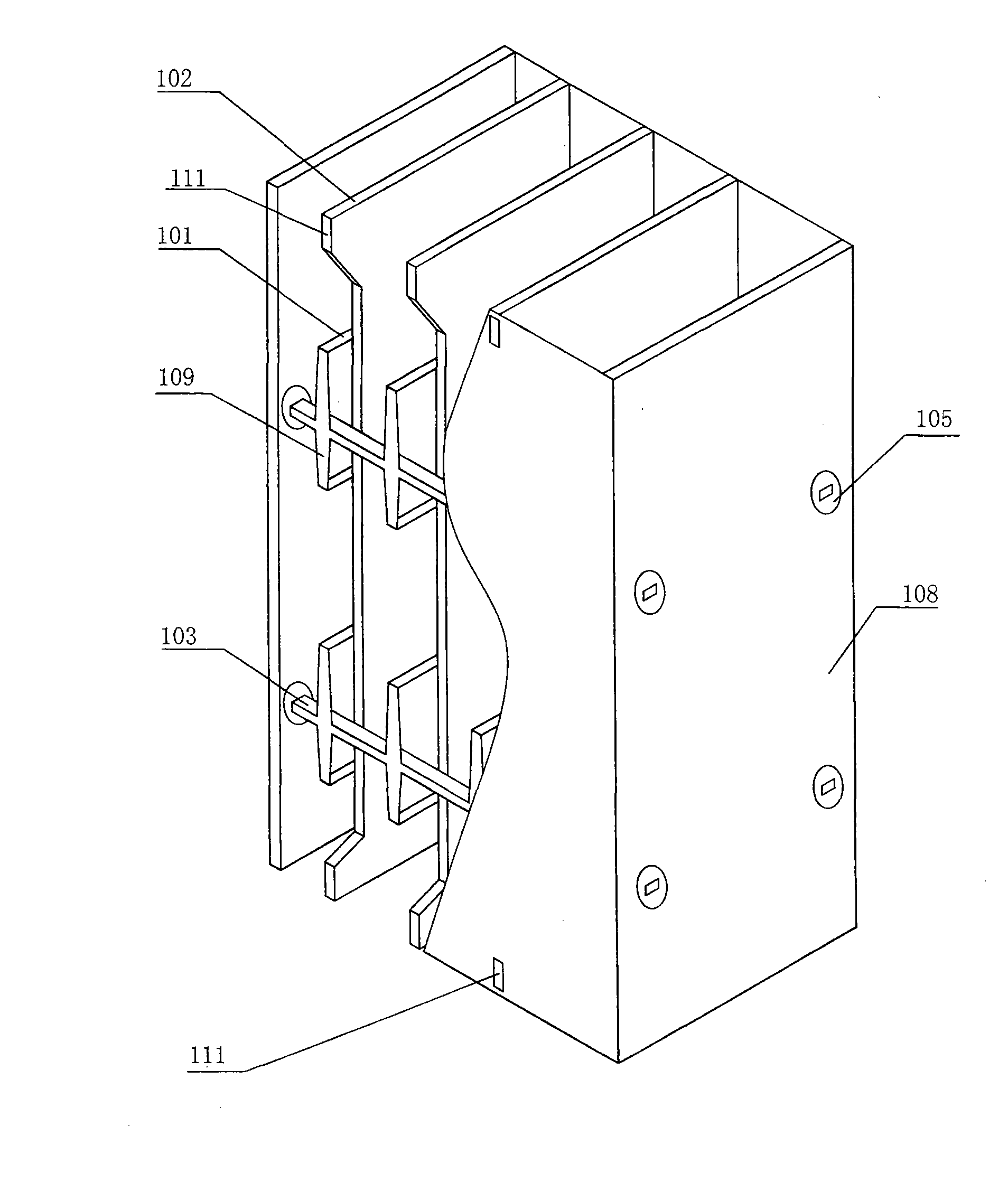
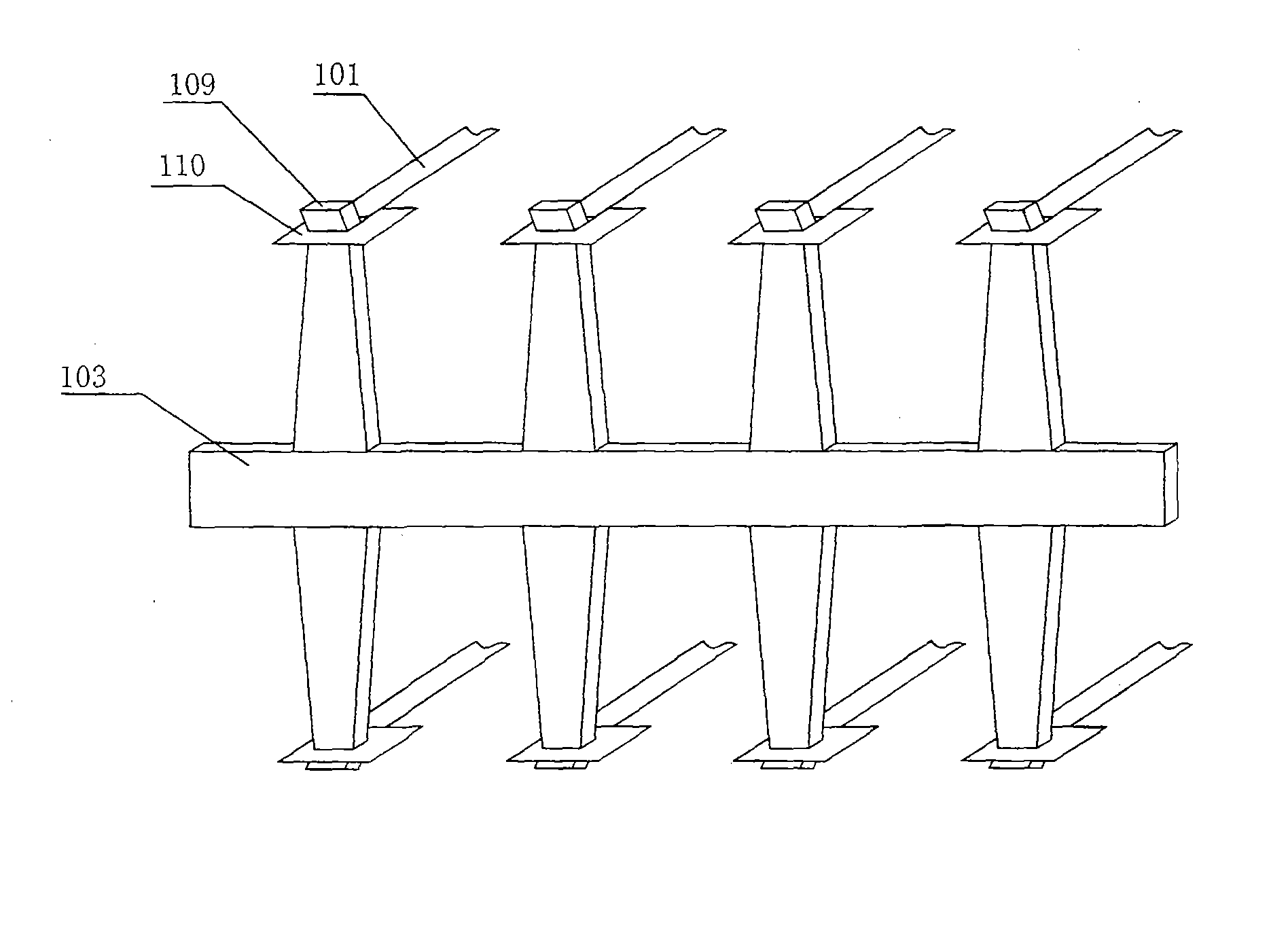
[0047] figure 1 It is a structural schematic diagram of the air duct type electronic air purifier of the present invention; figure 2 It is a three-dimensional structure diagram of a plasma reactor half section of the present invention; image 3 yes figure 2 Schematic diagram of the conductive rail structure for preventing microdischarge.
[0048] As shown in the figure, the plasma air disinfection and purification air conditioner includes 1. Air duct type electronic air cleaner, including plasma reactor 1, pulse power supply 2, air inlet 5 with air inlet air filter 7, and air outlet 6 with Air outlet air filters 4 are all installed in the casing 3 . The plasma reactor 1 is arranged on the wind deflector 8, the high voltage output end of the pulse power supply 2 is electrically connected with the plasma reactor 1, and the plasma reactor 1 is arranged in the air flow duct. The described plasma reactor 1 is provided with a positive electrode 101 and a negative electrode 102...
Embodiment 2
[0052] The micro-discharge conductive rail 103 of the present invention is provided with convex portions 109 arranged equidistantly, and the two ends of the positive electrode 101 are the tops of the convex portion 109 respectively fixed on the corresponding conductive rail; the convex portion of the micro-discharge conductive rail 103 is prevented 109 are set as one group of two up and down symmetrical ones, and n groups are set up for each convex portion 109 that prevents the micro-discharge conductive rail 103, and the top of the convex portion 109 is provided with an outward bend. The two ends of the positive electrode 101 are provided with a stainless steel connection frame 110 , and a square hole is punched in the middle of the stainless steel connection frame 110 . A protruding negative electrode fixing pin 111 is provided on the upper and lower ends of the negative electrode 102 adjacent to the reactor shell 108, and the corresponding part of the reactor shell 108 is pr...
Embodiment 3
[0056] Figure 4 It is a three-dimensional structure diagram of another embodiment of the plasma reactor of the present invention. As shown in the figure, the described anti-micro-discharge conductive rail 103 is provided with recesses arranged equidistantly, and the concave portions are provided with n groups. The two ends of the micro-discharge conductive rail 103 are fixed and electrically connected with four positive electrode metal supports 104 which are orthogonally arranged around the reactor; Discharge conductive rail fixed ring 107, prevent micro-discharge conductive rail fixed ring 107 from equidistantly adjacent to prevent micro-discharge conductive rail 103; each positive electrode metal support 104 is provided with an insulating connector 105 and two ends respectively. The corresponding mounting holes of the housing 108 are fixed. An insulating connector fixing bolt 106 is provided to fasten the insulating connector 105 on the metal reactor shell 108 .
[0057] T...
PUM
| Property | Measurement | Unit |
|---|---|---|
| width | aaaaa | aaaaa |
| thickness | aaaaa | aaaaa |
| dust removal efficiency | aaaaa | aaaaa |
Abstract
Description
Claims
Application Information
 - R&D
- Intellectual Property
- Life Sciences
- Materials
- Tech Scout
- Unparalleled Data Quality
- Higher Quality Content
- 60% Fewer Hallucinations
Browse by: Latest US Patents, China's latest patents, Technical Efficacy Thesaurus, Application Domain, Technology Topic, Popular Technical Reports.
© 2025 PatSnap. All rights reserved.Legal|Privacy policy|Modern Slavery Act Transparency Statement|Sitemap|About US| Contact US: help@patsnap.com


