A test method for power frequency magnetic field immunity based on frequency deviation

A technology of frequency deviation and power frequency magnetic field, which is applied in the field of power frequency magnetic field immunity test based on frequency deviation, can solve the problems that cannot be determined in advance, it is difficult to eliminate the risk of misjudgment, and the method of synchronization is not ideal, so as to eliminate the test blind zone , good consistency, and the effect of resolving uncertainty

Inactive Publication Date: 2020-03-20
NR ELECTRIC CO LTD +1
View PDF4 Cites 0 Cited by
  • Summary
  • Abstract
  • Description
  • Claims
  • Application Information

AI Technical Summary

Problems solved by technology

When testing according to these standards, a single test is often used as the test result, so the above-mentioned problems have certain concealment and harmfulness.
However, because when the sampling amplitude and phase distortion are the largest, the corresponding phase angle difference is related to the specific sample and cannot be determined in advance (see the previous analysis)
Therefore, this method is still difficult to present the situation where the sample sampling distortion is the largest, and it is difficult to eliminate the risk of misjudgment
And the synchronous signal source and the interference source need to be associated with the two. The conventional power frequency magnetic field immunity test platform (referring to GB / T 17626.8 or IEC 61000-4-8 and other commonly used power frequency magnetic field immunity test standards) In the test platform), the signal source and the interference source are independent of each other. If synchronization is required, special transformation is required
Therefore, the method based on the synchronization of the signal source and the interference source is still not ideal.

Method used


Image

  • A test method for power frequency magnetic field immunity based on frequency deviation
  • A test method for power frequency magnetic field immunity based on frequency deviation
  • A test method for power frequency magnetic field immunity based on frequency deviation

Examples


Embodiment 1

[0083] 1. The relevant information of the test is as follows:

[0084] Sample: analog input type merging unit (three-phase current); rated power frequency (f 0 ): 50Hz;

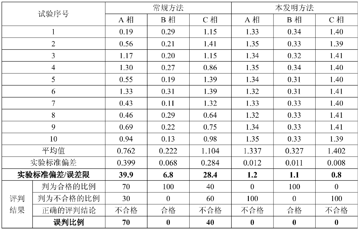
[0085]Acceptance criteria: under the rated current (1A) of the three-phase current, the absolute value of the amplitude error is not greater than 1% (error limit);

[0086] Test level: 1000A / m; (given magnetic field strength)

[0087] Test time: T test = 3 seconds;

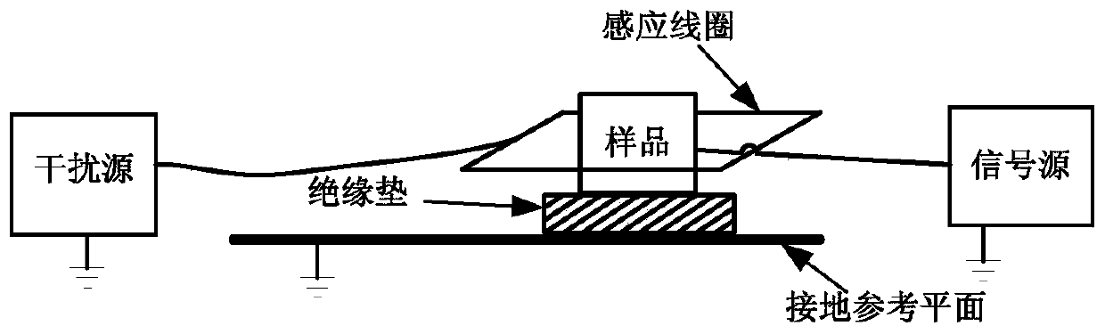
[0088] Interference source: MV 2616 (adjustable transformer) + UCS500M (control circuit) + RFTVS-Spezial (converter) + frequency converter;

[0089] Induction coil: MS 100 (square, single-turn induction coil);

[0090] Induction coil factor: 0.87m -1 ;

[0091] Signal source: CM256plus relay protection tester;

[0092] Monitoring tool: calibrator.

[0093] Note: The above acceptance criteria, test level and test time are all part of the inspection requirements.

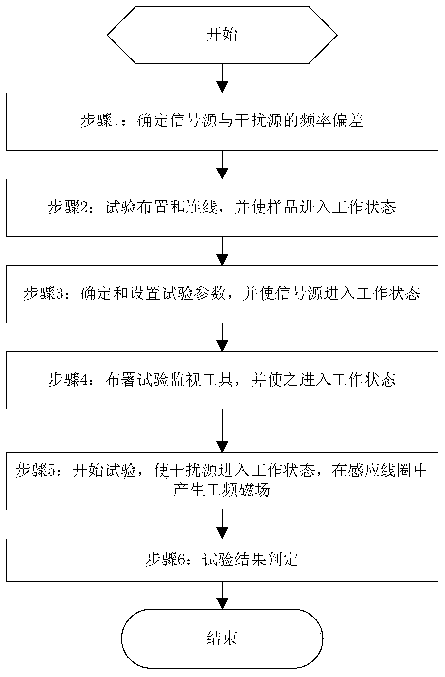
[0094] 2. The following is the specific implementation process:

[0095] ...


PUM


Abstract

The invention discloses a frequency offset based power frequency magnetic field immunity test method. The method is characterized by comprising the steps that 1) a frequency offset between a signal source and an interference source is determined; 2) test is arranged, lines are connected, and a sample is in a working state; 3) a test parameter is determined and set, and a signal source enters a working state; 4) a test monitoring tool is disposed and enters the working state; 5) test is started, the interference source enters the working state, and a power frequency magnetic field is generatedin an induction coil; and 6) a test result is determined, and after test, test data is extracted from the test monitoring tool disposed in the step 4, the test data is evaluated according to examination requirements, and a test conclusion is obtained, namely, the test sample is determined to be qualified or unqualified. According to the invention, a test blind area is eliminated from the power frequency magnetic field immunity test, and the test result is highly consistent.

Description

technical field [0001] The invention relates to the field of electromagnetic compatibility detection, in particular to a power frequency magnetic field immunity test method based on frequency deviation. Background technique [0002] The power frequency magnetic field immunity test is one of the basic electromagnetic compatibility test items. The purpose of this test is to test the performance of the equipment in the power frequency magnetic field environment. [0003] GB / T 17626.8 "Electromagnetic compatibility test and measurement technology power frequency magnetic field immunity test (idt IEC61000-4-8)" or IEC 61000-4-8 "Electromagnetic compatibility (EMC)-Part 4-8: Testing and measurement techniques- "Power frequency magnetic field immunity test" is the basic method standard, which is often quoted (directly or indirectly) for the power frequency magnetic field immunity test method standard. Its purpose is to establish a common and repeatable benchmark to evaluate the Pe...

Claims


Application Information

Patent Timeline
Patent Type & Authority Patents(China)
IPC IPC(8): G01R35/04
CPCG01R35/04
Inventor 邓代记刘杲培陈志锋邓颖宁于哲笃峻
Owner NR ELECTRIC CO LTD
Why Eureka
Try Eureka