
Computer case

A computer and chassis technology, applied in the field of computer peripherals, can solve problems such as low work efficiency, accumulation of dust in accessories, and inconvenient maintenance, and achieve the effects of improving work efficiency, reducing noise, and facilitating maintenance or replacement.

Inactive Publication Date: 2018-06-12
重庆熊猫快收供应链管理有限公司
View PDF3 Cites 3 Cited by
  • Summary
  • Abstract
  • Description
  • Claims
  • Application Information

AI Technical Summary

Problems solved by technology

[0002] The main frame of the existing computer is generally a one-piece box, and the side of the box body is generally fixed with a detachable cover plate by screws. Computer accessories such as hard disks, motherboards, optical drives, and power supplies are placed inside the box body. It is directly fixed inside the chassis. When the accessories inside the chassis are damaged and repaired or replaced, the side panels of the chassis need to be disassembled to take out the computer accessories. A screwdriver is required for both opening and installation, which is inconvenient, time-consuming, and laborious for maintenance, which makes the work efficiency low
In addition, if you use the case for a long time, the accessories will accumulate dust. Because the side panels of the case are troublesome to disassemble, if you don’t clean the case for a long time under normal circumstances, it is easy to cause damage to the accessories due to poor heat dissipation

Method used


Image

  • Computer case
  • Computer case
  • Computer case

Examples


Embodiment 1

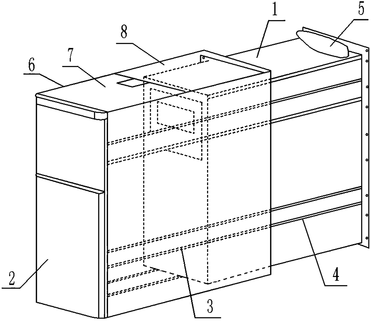
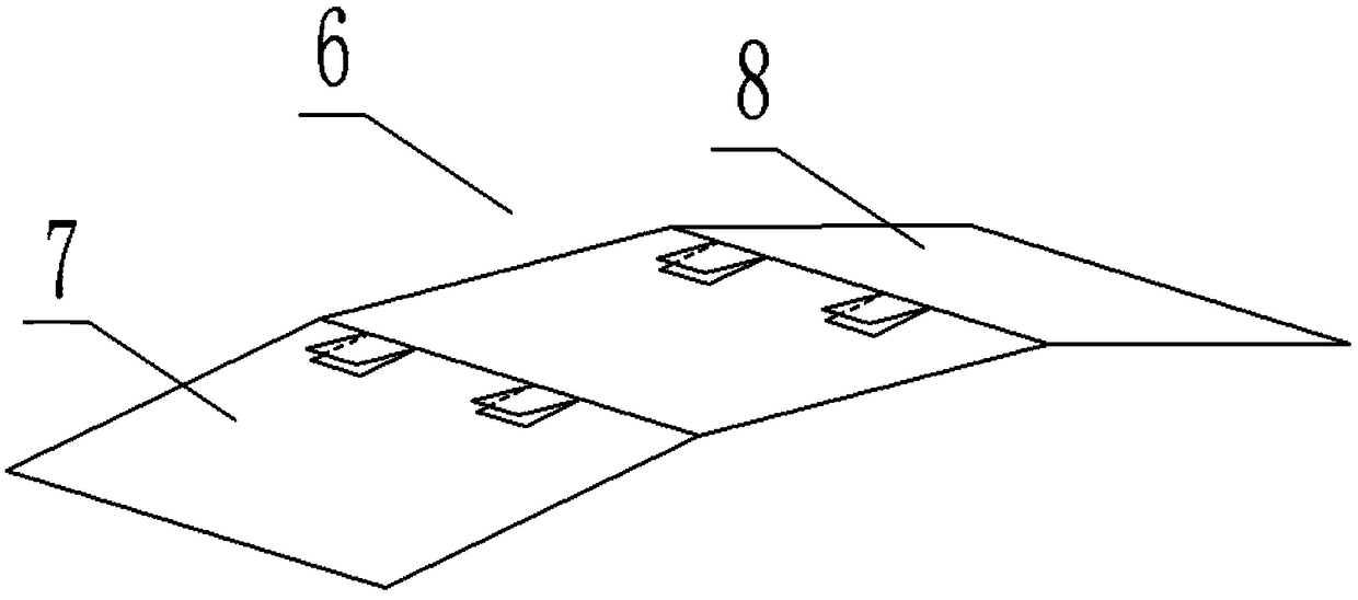
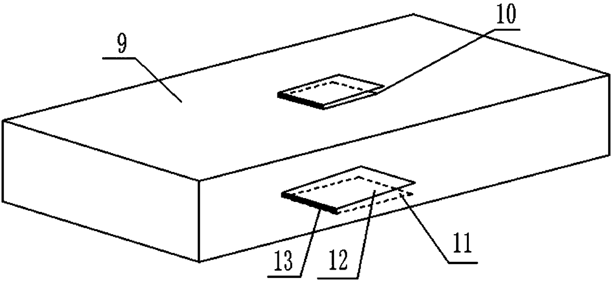
[0025] Embodiment 1 The reference signs in the drawings include: box body 1, shell 2, groove 3, guide rail 4, air bag 5, upper cover 6, first shutter 7, second shutter 8, elastic box 9 , Upper opening 10, lower opening 11, blocking plate 12, fixed key 13.

[0026] Such as figure 1 As shown, a computer case includes a box body 1 and a casing 2. The shape of the box body 1 is consistent with that of the casing 2, and only the shape of the box body 1 is slightly smaller than the size of the casing 2, so that the box body 1 can be movably connected to the box through a guide rail. Inside the casing 2, grooves 3 are provided on the bottom and right side of the box body 1, and a guide rail 4 corresponding to the groove 3 is provided on the inner surface of the casing 2. The guide rail 4 is a sliding linear guide rail, and its cross-sectional shape can be rectangular , triangle or other shapes, of course, the guide rail 4 can also be set to a rolling guide rail, similar to various g...

Embodiment 2

[0031] Embodiment 2 The reference signs in the drawings also include: push button switch 14 , spring 15 , door cover 16 , and cooling hole 17 .

[0032] Such as Figure 4 As shown, a computer case, the difference between the present embodiment and the first embodiment is that an electric telescopic rod is installed on the left side of the upper cover plate 6 of the casing 2, and the electric telescopic rod includes a button switch 14 and a spring 15, and the button switch 14 is electrically An electromagnet is connected, the button switch 14 is arranged at the rear end of the second shutter 8, the spring 15 is fixed on the left side of the upper cover 6, and an iron block is welded on the left end of the spring 15, which can be pressed when the air bag 5 expands Button switch 14, the button switch 14 is energized, and the electromagnet generates magnetism and attracts the iron block, so that the spring 15 is compressed and shortened to the right, driving the shutter to arch up...


PUM


Abstract

The invention relates to the field of computer peripheral equipment, and discloses a computer case. The computer case further comprises a shell, the rear side face of the shell is open, the front sideface of the shell is provided with a window, an upper cover plate of the shell is formed by hinging at least two shielding plates end to end in sequence, and the front end of the upper cover plate ishinged to the shell; a hinge end of one shielding plate is provided with an opening, and a hinge end of the other shielding plate hinged to the shielding plate is provided with a clamping block clamped in the opening; the inner side face of a hinge end of the upper cover plate is provided with an elastic box, the upper side face of the elastic box is provided with an upper opening located in theopening, the lower side face of the elastic box is provided with a lower opening, and the upper opening and the lower opening are provided with non-return devices which can only be opened upwards; a box body is movably connected into the shell through a guide rail, one side face of the box body is open, and the rear end of the box body is provided with an airbag capable of being in contact with the rear end of the upper cover plate. By means of the technical scheme, accessories in the case are conveniently maintained or replaced, and the heat dissipation and dust proof effects of the case areimproved.

Description

technical field [0001] The invention relates to the field of computer peripherals, in particular to a computer case. Background technique [0002] The main frame of the existing computer is generally a one-piece box, and the side of the box body is generally fixed with a detachable cover plate by screws. Computer accessories such as hard disks, motherboards, optical drives, and power supplies are placed inside the box body. It is directly fixed inside the chassis. When the accessories inside the chassis are damaged and repaired or replaced, the side panels of the chassis need to be disassembled to take out the computer accessories. Opening and installation all have to use a screwdriver, and there are problems of inconvenient, time-consuming and laborious maintenance during maintenance, which makes the work efficiency low. Moreover, if the case is used for a long time, the accessories will accumulate dust. Since the side panels of the case are troublesome to disassemble, if ...

Claims


Application Information

Patent Timeline
Patent Type & Authority Applications(China)
IPC IPC(8): G06F1/18
CPCG06F1/181G06F1/183
Inventor 任宏伟
Owner 重庆熊猫快收供应链管理有限公司
Learn More