Power distribution cabinet convenient in maintenance and heat dissipation

A power distribution cabinet and body technology, which is applied in the field of power distribution cabinets that are easy to maintain and dissipate heat, can solve the problems that the heat of the power distribution cabinet cannot be dissipated in time, the staff is inconvenient to work, and the wires are self-burning and destroyed, and the structure is compact and practical. The effect of strong sex and stable working condition

Inactive Publication Date: 2018-06-12
MINGGUANG JIAYI ELECTRIC CONTROL TECH
View PDF4 Cites 5 Cited by
  • Summary
  • Abstract
  • Description
  • Claims
  • Application Information

AI Technical Summary

Problems solved by technology

[0005] Aiming at the deficiencies of the prior art, the present invention provides a power distribution cabinet that is convenient for maintenance and heat dissipation, which solves the problem that the power distribution cabinet will generate a lot of heat after a long period of use, and the heat dissipation function of the existing power distribution cabinet is not good. The heat in the power distribution cabinet cannot be dissipated in time, and it is easy to cause the internal temperature of the power distribution cabinet to be too high, causing the wires to burn and destroy, which affects people's electricity consumption. Since the power distribution cabinets are usually fixed at high places, When the main body of the power distribution cabinet needs to be repaired, it is necessary for the staff to use foreign objects to ascend the height to repair the power distribution cabinet, which brings inconvenience to the work of the staff

Method used


Image

  • Power distribution cabinet convenient in maintenance and heat dissipation
  • Power distribution cabinet convenient in maintenance and heat dissipation

Examples


Embodiment Construction

[0025] The following will clearly and completely describe the technical solutions in the embodiments of the present invention with reference to the accompanying drawings in the embodiments of the present invention. Obviously, the described embodiments are only some of the embodiments of the present invention, not all of them. Based on the embodiments of the present invention, all other embodiments obtained by persons of ordinary skill in the art without making creative efforts belong to the protection scope of the present invention.

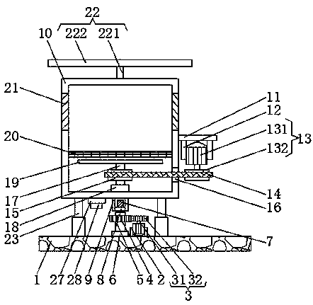
[0026] like Figure 1-2As shown, the present invention provides a technical solution: a power distribution cabinet that is convenient for maintenance and heat dissipation, including a base plate 1, the upper surface of the base plate 1 is fixedly connected to the bottom ends of the two first fixing rods 2, and the two second fixing rods The opposite surfaces of a fixed rod 2 are respectively fixedly connected with the left and right sides of the ...


PUM


Abstract

The invention discloses a power distribution cabinet convenient in maintenance and heat dissipation. The power distribution cabinet comprises a bottom plate. The upper surface of the bottom plate is fixedly connected with the bottom ends of two first fixed rods. The opposite surfaces of the two first fixed rods are fixedly connected with the left side face and the right side face of a first driving device respectively. The first driving device is meshed with a second gear, and a first rotating shaft is clamped on the inner surface of the second gear. The outer surface of the first rotating shaft is connected with a first bearing in a sleeved mode. The first bearing is clamped on the upper surface of the bottom plate, and the top end of the first rotating shaft is fixedly connected with thebottom end of a threaded column. The power distribution cabinet is convenient in maintenance and heat dissipation. Based on the mutual cooperation of a first motor, a first gear, a second gear, a first rotating shaft, a threaded column, a second fixed rod, a power distribution cabinet body, a second motor, a driving wheel, a belt, a driven wheel, a second rotating shaft and fan blades, the heat inside the power distribution cabinet body can be conveniently dissipated. Therefore, the working personnel can conveniently maintain the power distribution cabinet body, and the work of the working personnel is facilitated.

Description

technical field [0001] The invention relates to the technical field of power distribution cabinets, in particular to a power distribution cabinet that is convenient for maintenance and heat dissipation. Background technique [0002] Power distribution cabinets (boxes) are divided into power distribution cabinets (boxes), lighting distribution cabinets (boxes) and metering cabinets (boxes), and are the final equipment of the power distribution system. The power distribution cabinet is a general term for the motor control center. The power distribution cabinet is used in the occasions where the load is relatively dispersed and there are few circuits; the motor control center is used in the occasions where the load is concentrated and there are many circuits. They distribute the electric energy of a certain circuit of the upper-level power distribution equipment to the nearest load. This level of equipment shall provide protection, monitoring and control of the load. [0003...

Claims


Application Information

Patent Timeline
Patent Type & Authority Applications(China)
IPC IPC(8): H02B1/30H02B1/56
CPCH02B1/303H02B1/30H02B1/565
Inventor 李兵
Owner MINGGUANG JIAYI ELECTRIC CONTROL TECH
Why Eureka
Try Eureka